
For the final project, I am going to build a better LED Nixie display. This is again, going to be heavily
influenced by the Cronixie project, and instead of a full clock display, I will just construct
one display, that can display the digits from 0 to 9, and can be controlled by a scroll wheel.
List of Materials needed:
20 WS2812B LEDs
1 100nF SMD Capacitor
1 49.9Ohm SMD Resistor
1 ISP header
1 Attiny85 IC
2 Copper PCB Blanks
The main improvement, will be if I can shrink the entire circuit up there, to a single copper blank,
which leaves me about 75x50mm of space to lay All that. The way I hope to do this, is by fitting the
Attiny85 onto the same board as the LEDS. On top of that, that one board will also have the ISP header
and two seperate power supplies, one for the LEDS and another for the Attiny85. Not to mention the 20
LEDs. I throught of doing a 7 Segment variant, which will be alot simpler, but I am not sure if the Parallax
offset from one plate to the next would make it look weird.
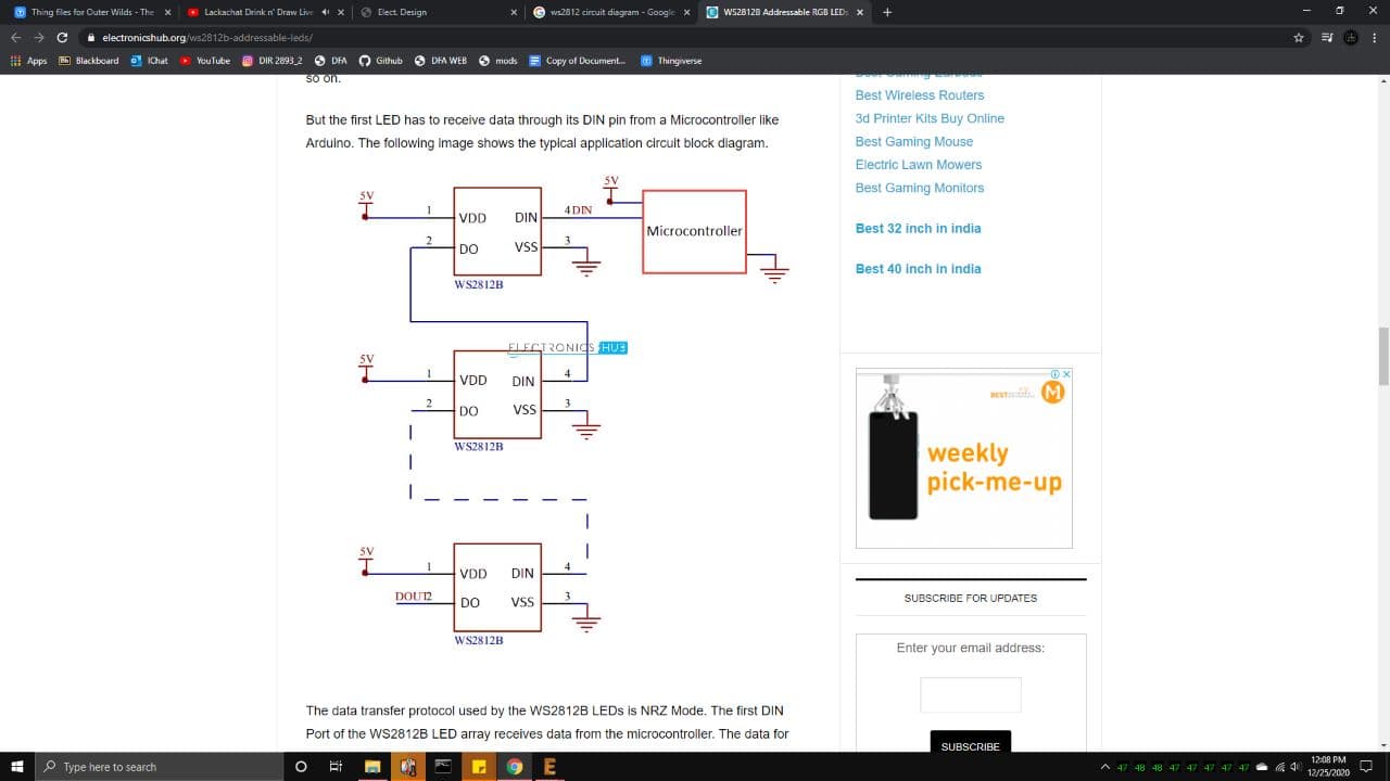
The circut should not be too difficult, Like last time it only needs 2 I/O pins, one for the LED data line,
and the other running an analogread for the scroll wheel. I'll also be using the WS2812 Neopixel LED, if I
cannot get it in a raw package, I might just get a bunch of them premade on a 3x3 matrix board, like last time,
but instead I will just desolder them from the board and solder them onto my circuit board.
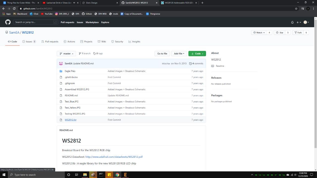
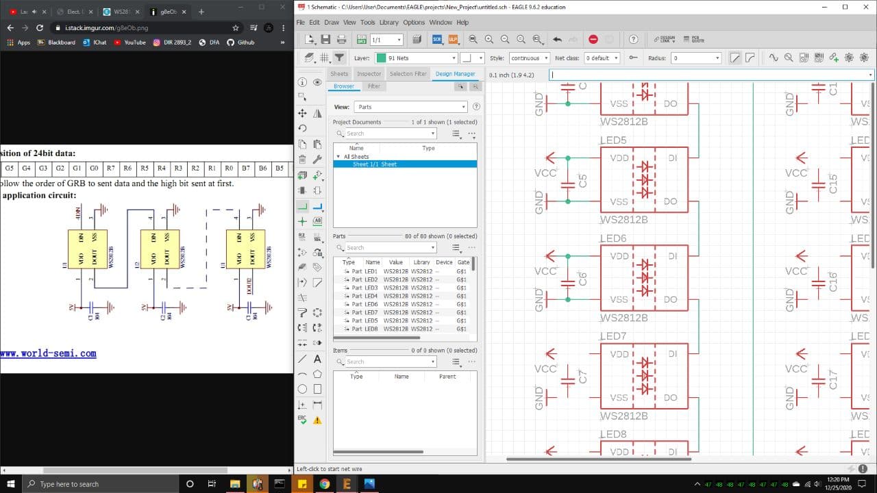
Before that, I designed a circuit schematic on eagle, and uses the footprint of the WS2812 LED, which I got
from this github page above.
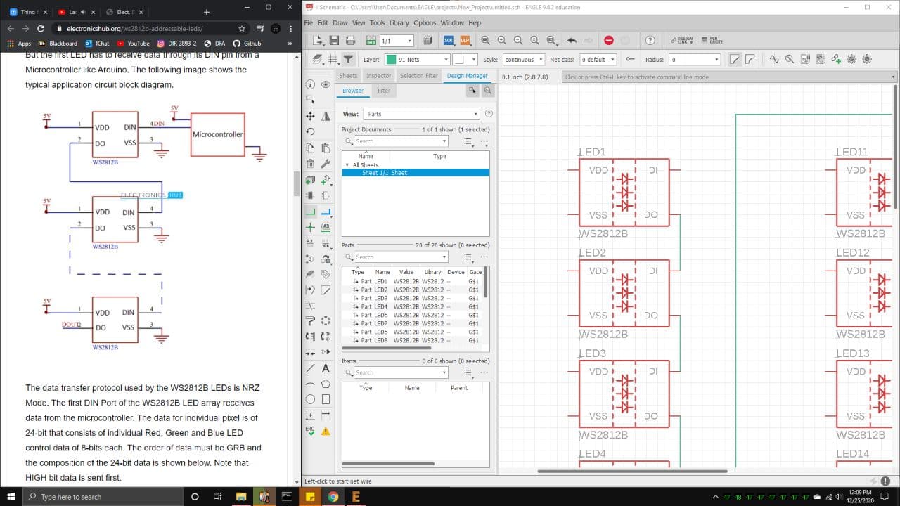
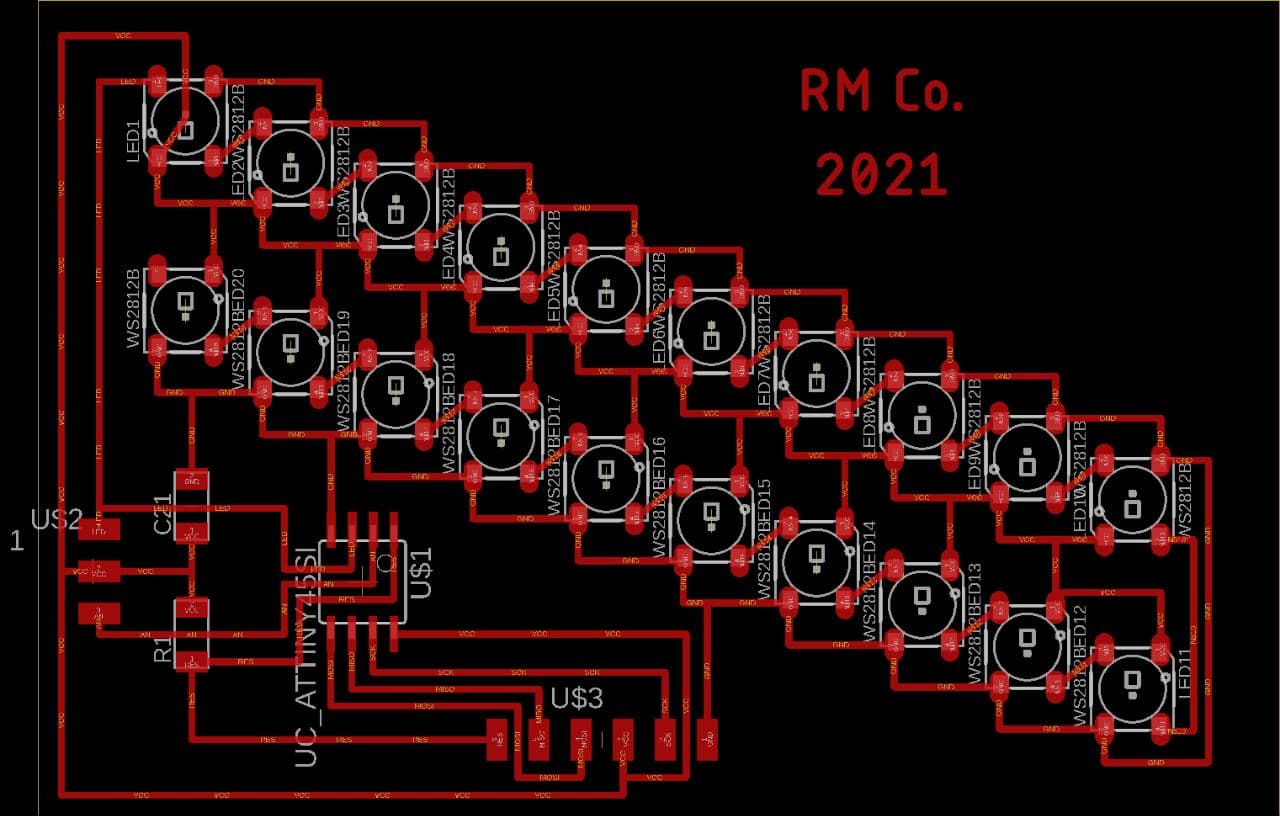
I ended up chaining the 20 LEDs together first, Dout into Din, to form this massive 20 LED strip, so in theory,
LEDs 0 and 19 will control number 0, and LEDs 9 and 10 control number 9.
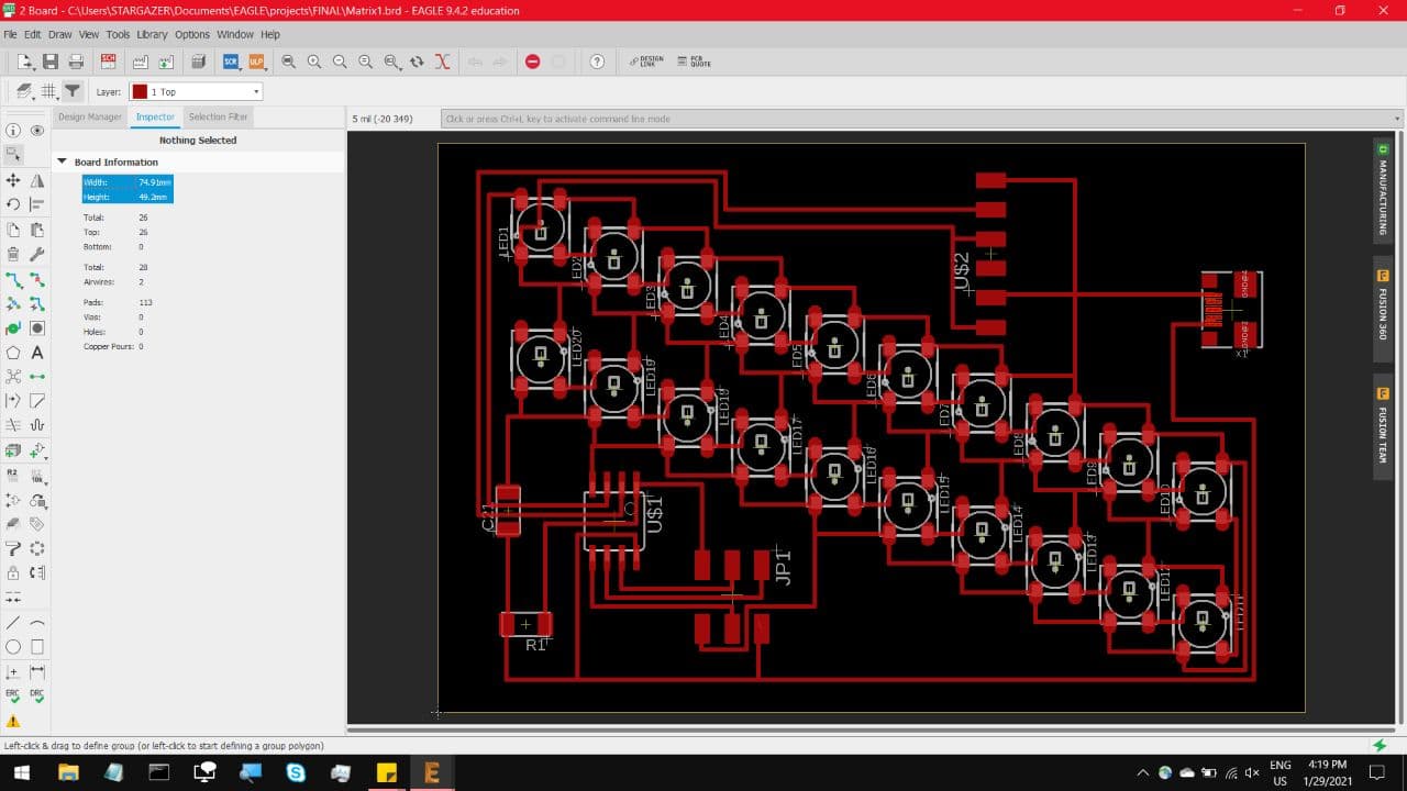
And here is the schematic with all the other stuff in it. I plan to run this off 2 power supplies, A barrel jack
sending a steady 5V to the LEDs, and a Micro USB sending 5V to the Attiny85.
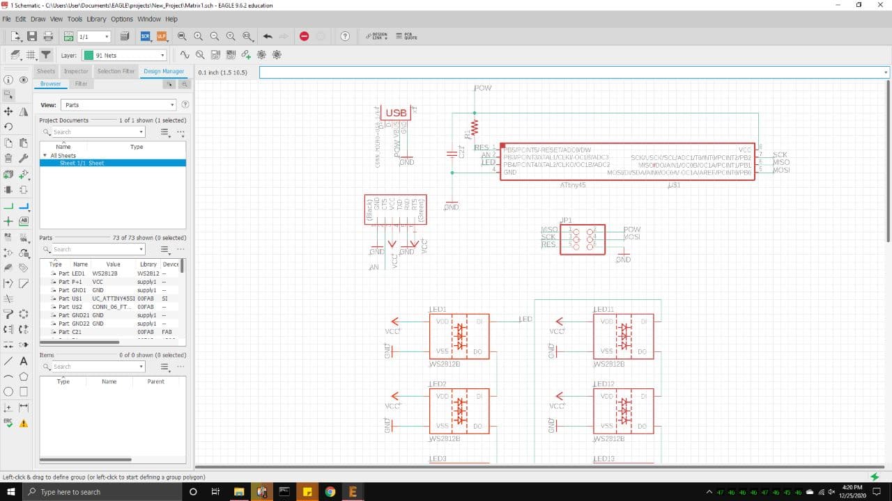
On some schematics it shows a capacitor between the Power and Ground pins on each LED, so I added it into the design
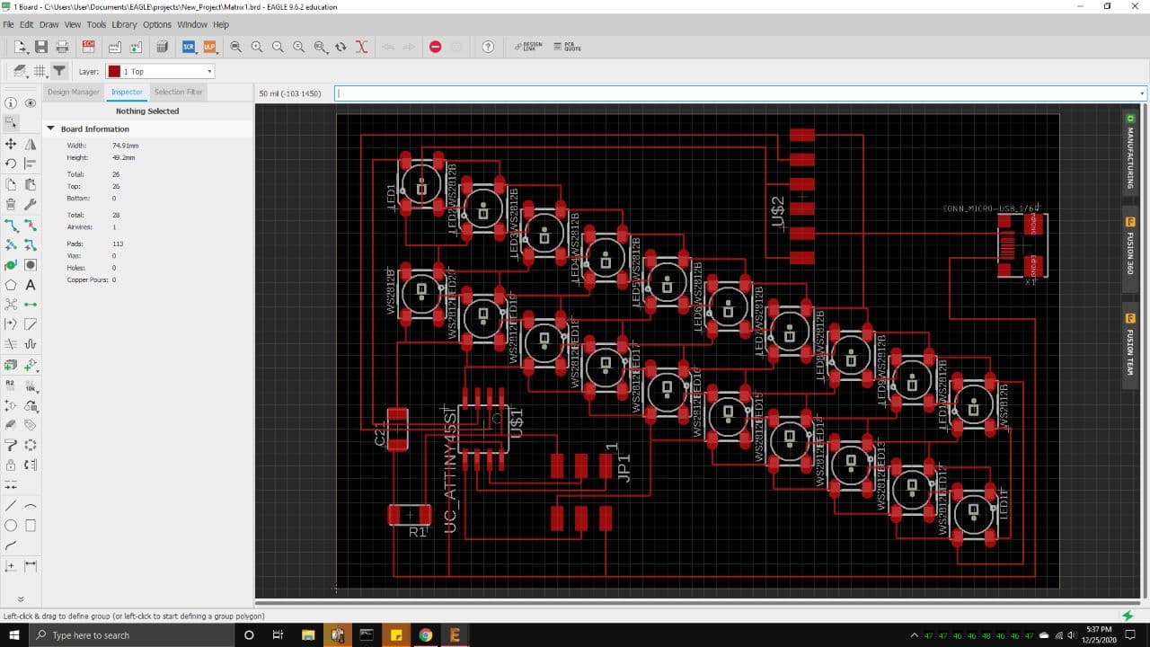
But I then realised it was gonna be a nightmare to untangle in the Board arrangement, so I decided to add a single large
capacitor between the 5V and ground pins of the LED chain. Here is the final Ratsnest, which just barely fits on a single
copper blank.
I have a feeling it will struggle to cut properly around the IC chip, so I might set it to cut on just 1 pass.
The 6 pin header pads are just there to help with soldering on Non Surface Mount components.
The pad right at the top and the second one from the bottom, those will be a common ground for both power supplies.
There will be a floating Barrel jack port which connects to the bottom 2 pads by wire, the lowest pad being the 5V.
The top 3 pads will be connected to a floating Variable Resistor by wire, which will serve as a scroll wheel for input.
The middle 2nd pad from the top is connected to the analog input on the Attiny85, while the pad just below it is connected
to the Barrel Jack power supply. This is only a first draft, this is just to help me get a rough understanding of How the
LED arrangement should look like, and how much space do I have left to work with.
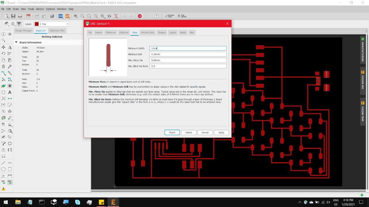
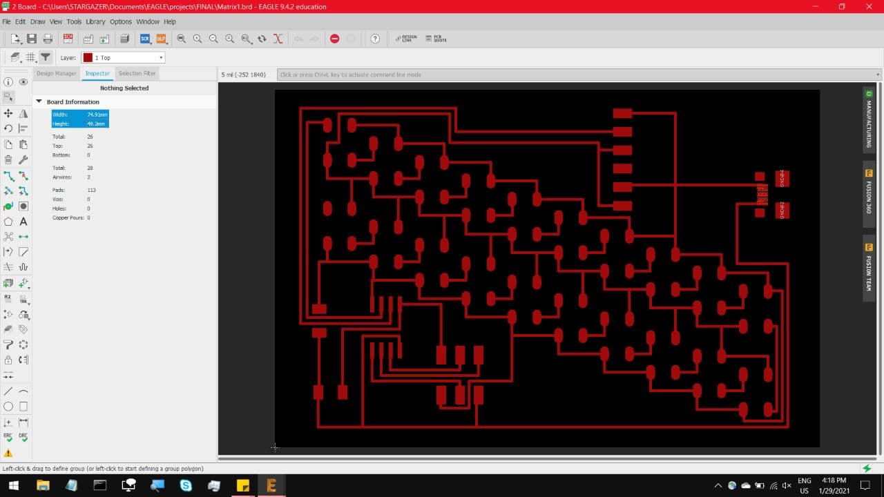
So, a few days have passed. First change, the PCB schematic failed 3 times, which I can only conclude to be because I mistyped
the trackwidth on DRC to be 6 instead of 16, that and a fouled out V bit.
So the ripup; command became very useful. Also, the total size of the board was fine
but calibrating the Stepcraft to ensure everything fit was a nightmare, so I shrunk the total size of the pattern. This is the DRC
with a track with set to 14 mil, which might be overkill but I was not about to take my chances.
And here is the rearranged pattern.
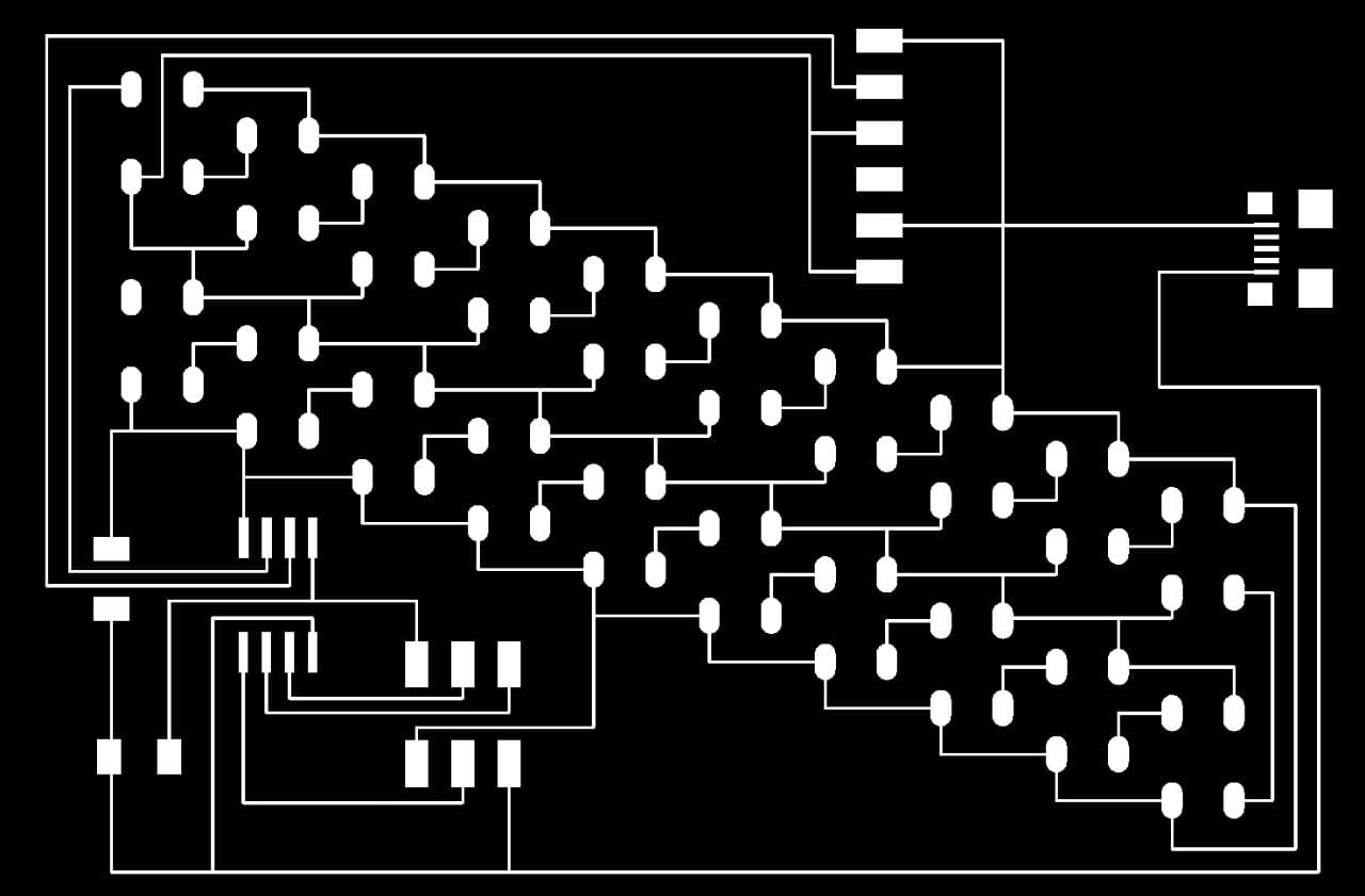
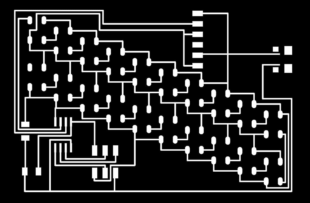
This is the what I expect to see on the final copper board.
You can see the changes I made when Comparing the 2 designs
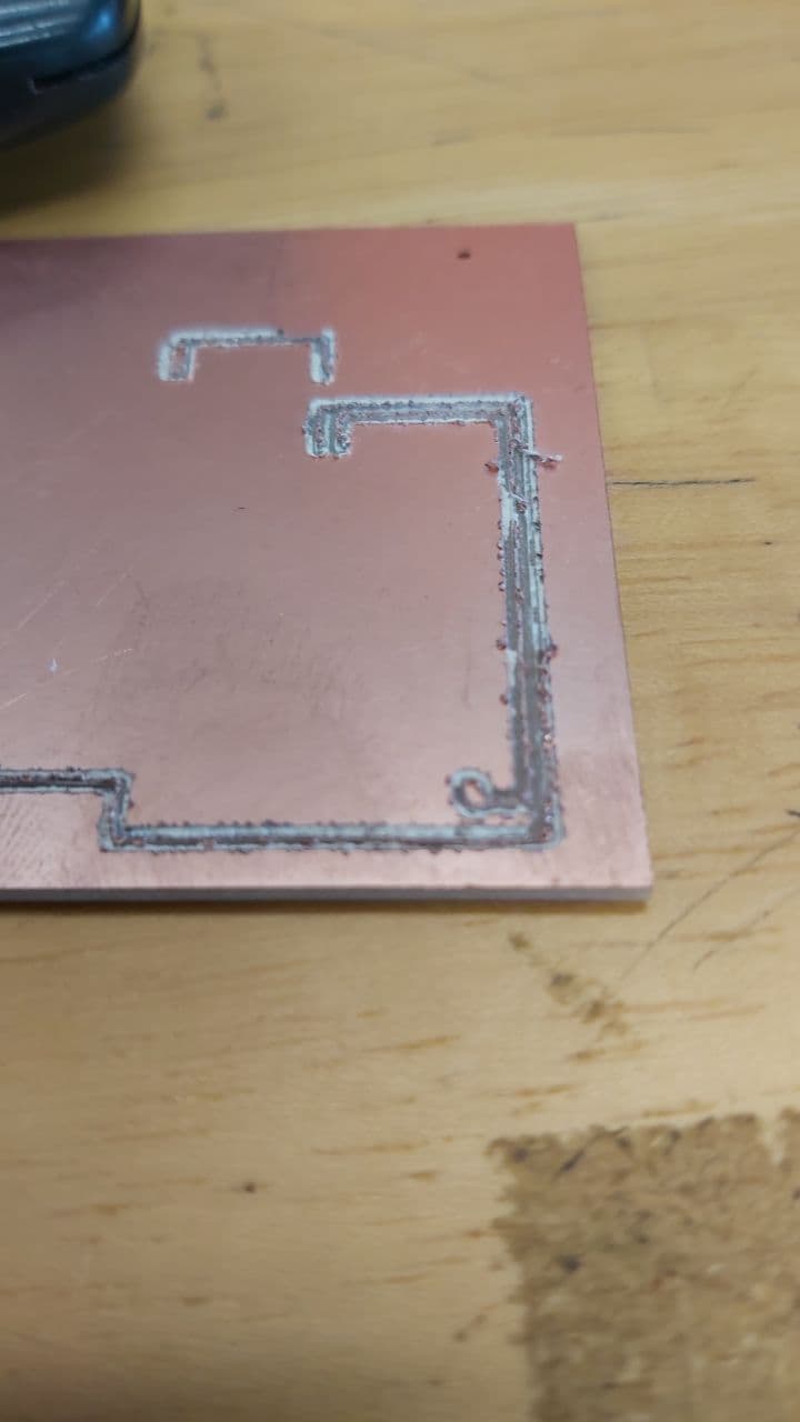
Moment of truth, and it turned out fantastic. Another big change was the Z depth, which I previously set to -0.05,
but even that was too deep. So I instead decided to recalibrate the Z height by putting a piece of folded receipt paper
under the calibrator cylinder. And immediately I noticed there was much less dust being kicked up by the bit.
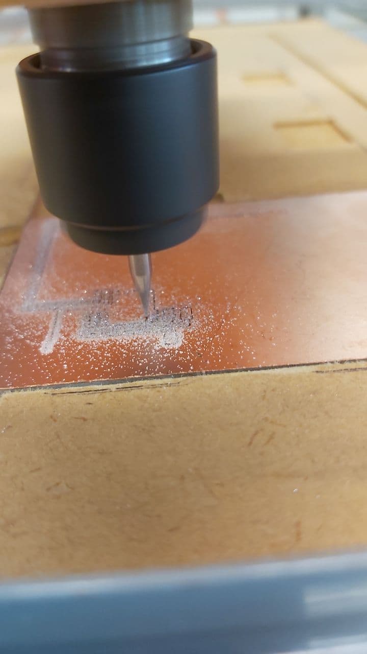
On top of that, the traces were so smooth, I could run it up against my finger and barely feel the cut.
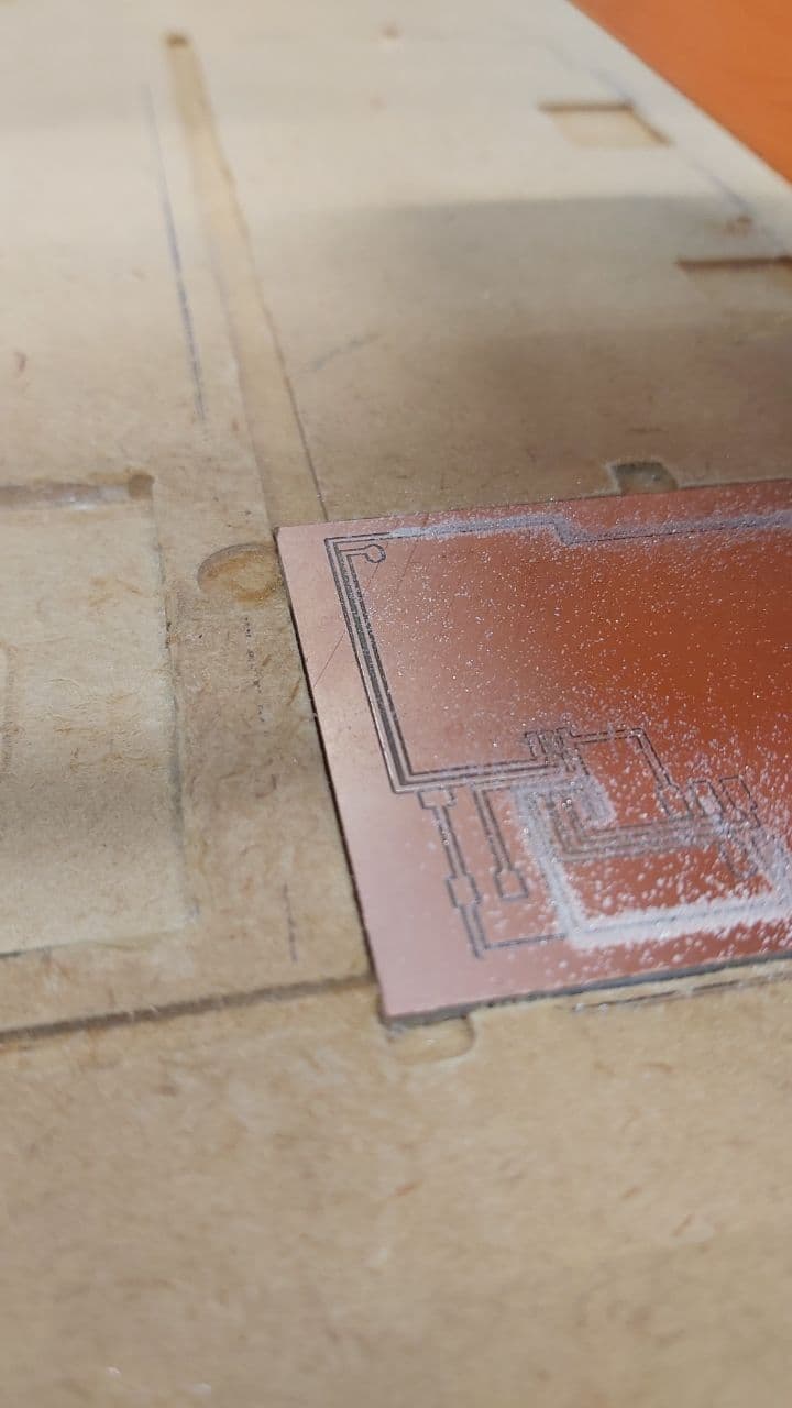
In total I ran 2 boards on the new pattern, the first had a slight Z inconsistency, causing some of the traces to only barely not cut.
But nothing a little penknife cannot fix, so this became the backup.
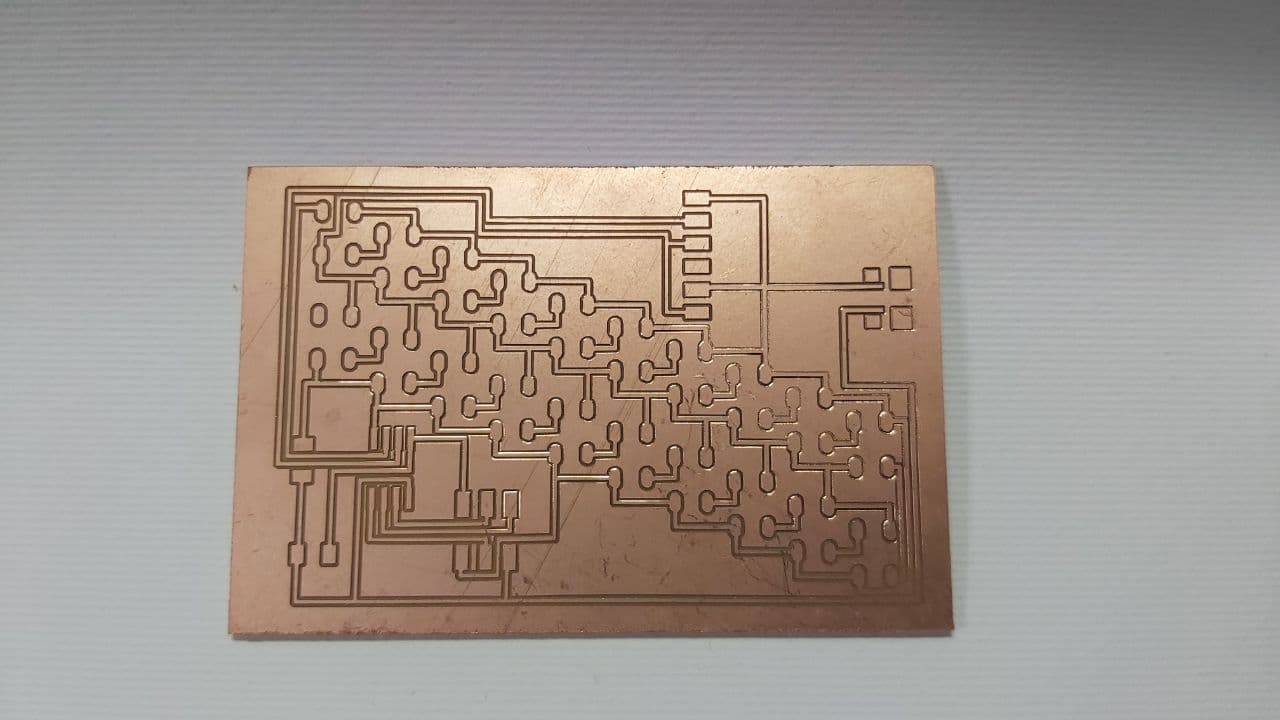
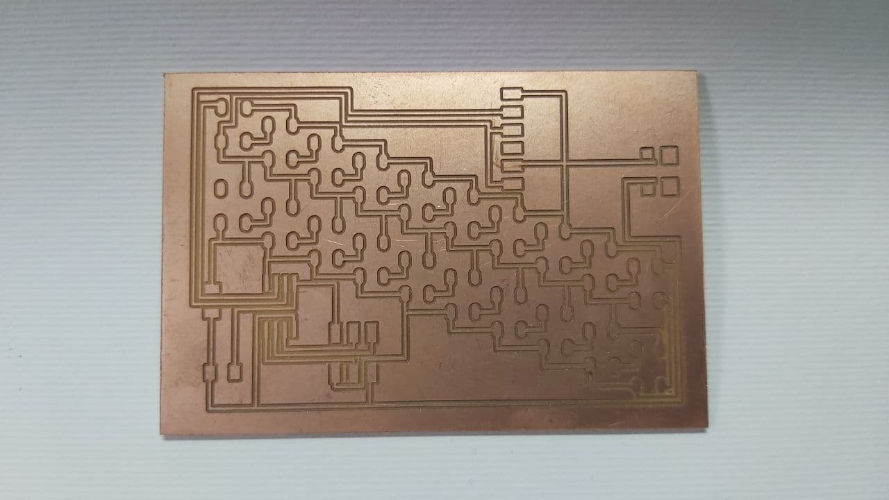
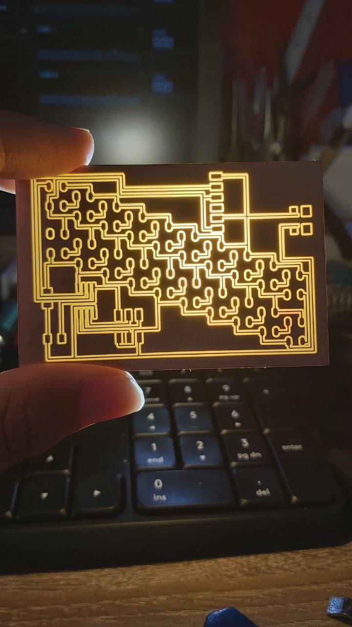
And here is the second board, which cut perfectly. Turns out it was just a matter of shifting the receipt paper around.
You can really see the difference when lit from behind, This is the one where it did not cut all the way through,
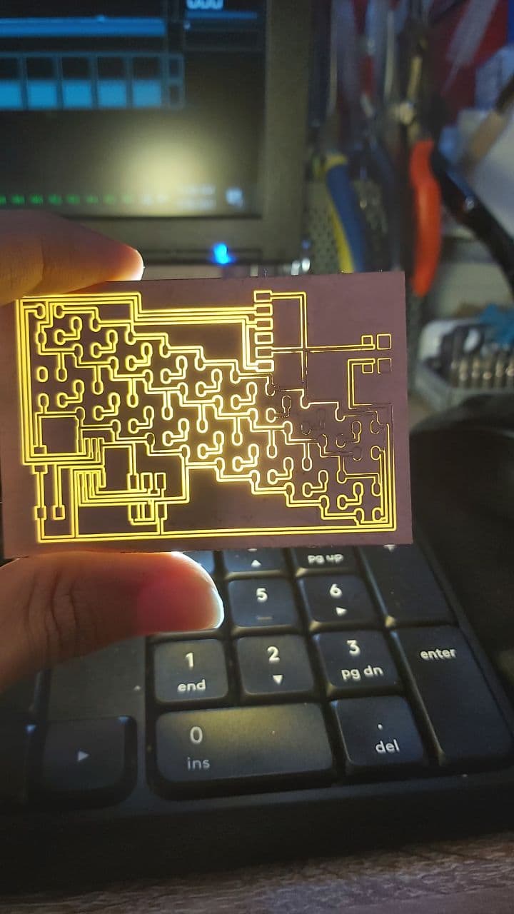
And this is the one with the clean cuts
Now it was time to start the code. I had to turn this hello board, into something that could run at least one data pin,
just so I could run the neopixels before I soldered them onto the final board.
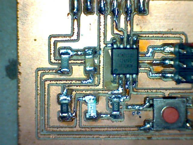
So, I chose to cut the line above the resistor leading to VCC, and rip off the bypass I soldered from that pin to the button.
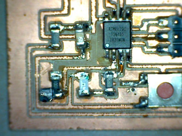
Then I soldered a pin to the pad leading straight to the 2nd pin on the IC, or in arduino, Pin 3.
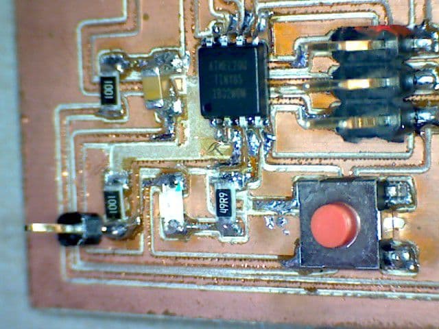
For the neopixels, the serial header on top would provide my VCC and GND, while the new pin would serve as the Din.
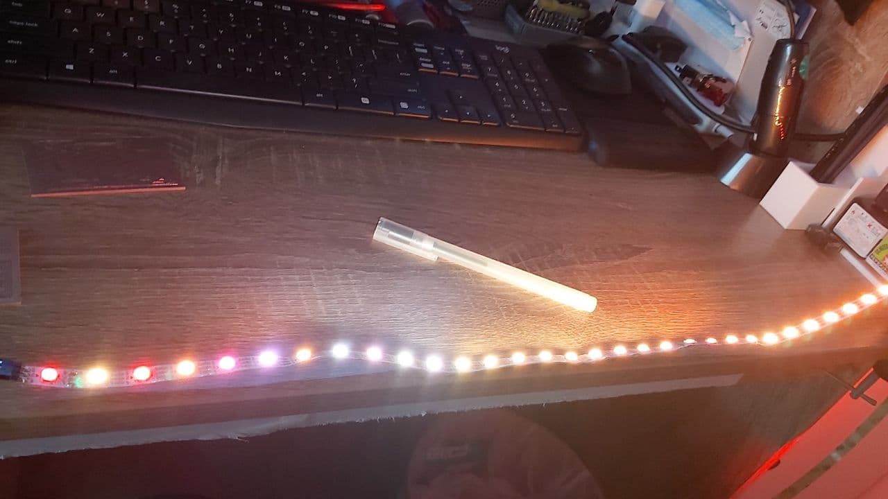
I first tested the neopixels strip I got on an Arduino Mega, and it worked surprisingly well for something I bought
from a scrap pile.
After a few days of trying to get the code to work and failing over and over again, I can now conclude that the set up
and running 20 neopixels off an attiny85 Is possible.
The first problem was for some reason windows updating tends to mess with your Avrdude toolchain, so I had to redo that.
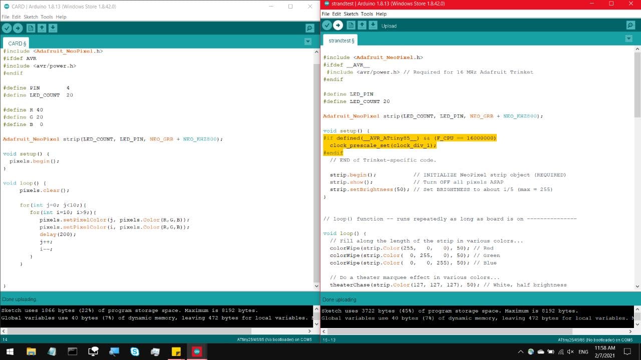
The second problem was that the two pieces of code I was looking at, they seem to have neem written by different people,
I got very confused when two pieces of almost identical code, used slightly differing Keywords as seen here,
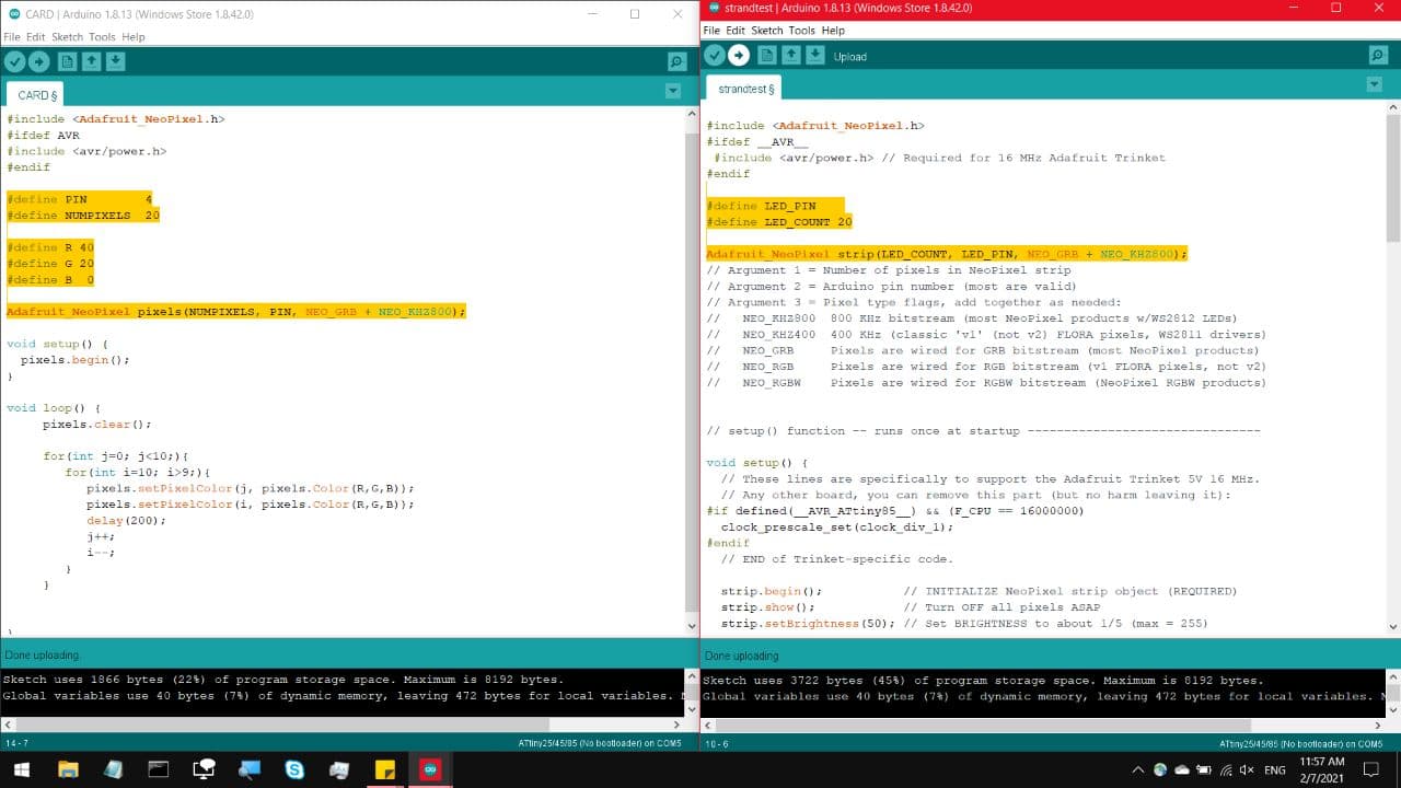
The other issue, One of the codes had an additional condition which made running on the attiny85 slightly different.
That and because the FastLED library from last semester, takes up a ridiculous amount of space on the attiny85, so
this project uses the not so different but fairly versatile Neopixel library from Adafruit, which can be downloaded
directly from the Arduino Library manager.
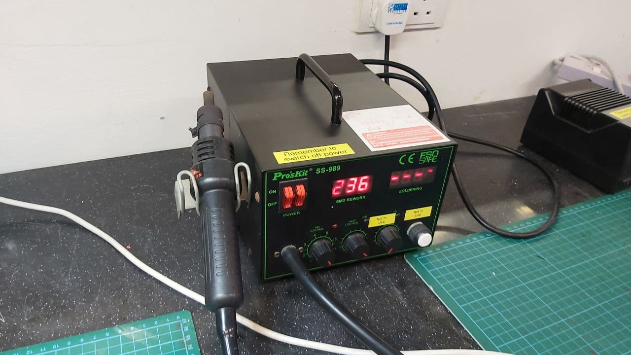
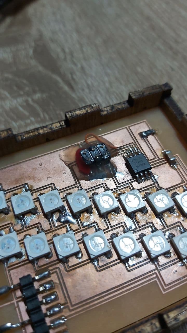
Now, there are a few ways to desolder SMD components, the way I did it was by blasting the strip with a hot air gun,
and then banging the strip on the table to fling the LED off the strip once the solder joints are melted. Do note that
this also flings small chunks of molten solder everywhere, and onto your hand.
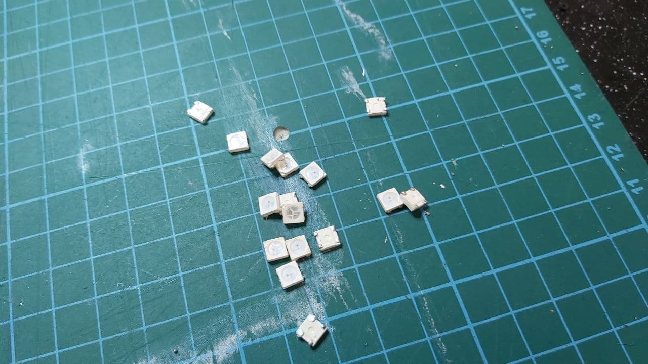
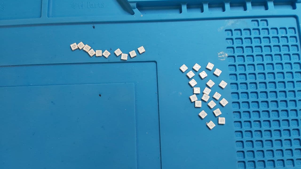
The main issue with the hot air gun is that it tends to damage, fragile SMD components, and out of about 31 I desoldered Only about 21 didnt get completely melted through. So perhaps next time, run the hot air gun on a lower heat. The ones on top left cluster, most of the wirebonds on the silicon chip looked to be completely destroyed.
The next issue, turns out the Eagle library I used for the WS2812B library had the package diagram placed upside down, which
meant that I soldered all 20 LEDs on upside down. You'll notice on the schematic earlier, the notches on the LEDs were faced
inwards against each other, but in real life, the notches are supposed to be face out away from each other.
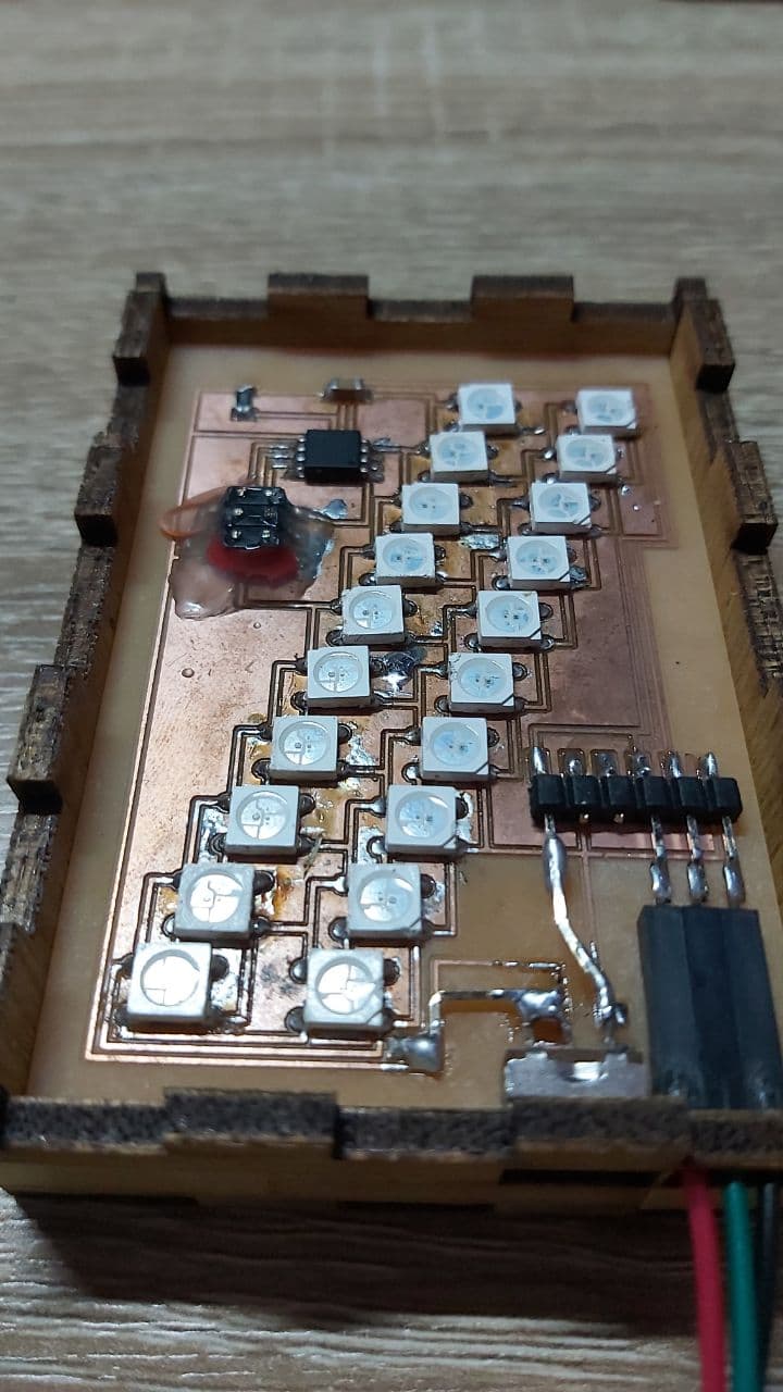
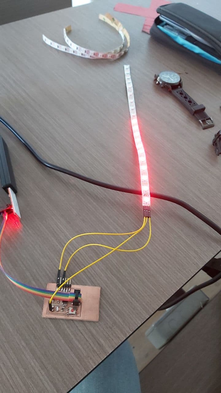
So after applying the New code to the fixed board, this was extremely satisfying to see.
Now for the housing, a neat trick for getting the position for SMD components on Fusion 360, open the circuit file as
a canvas,
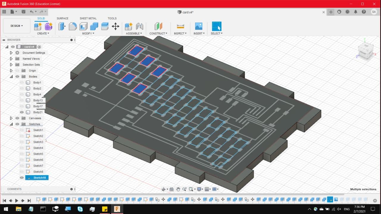
And sketch out the approximate size of the component over the pad positions. Thankfully WS2812B LEDs are consistently
5x5mm. And now you have a generally close position of the SMD LEDs
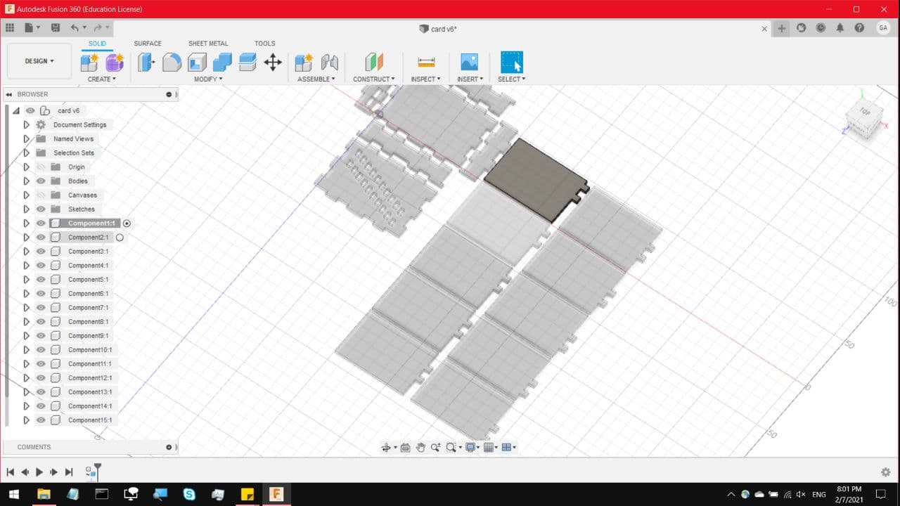
And we can finish off the rest of the body and plug points. The body can be much thinner, but I left about 7mm of spacing
to put some weights under the circuit board.
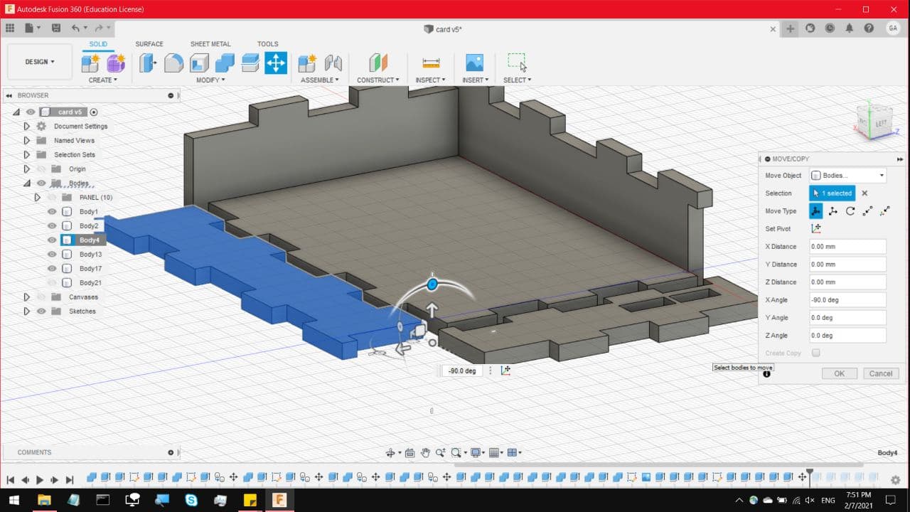
Next, a quick way to create a single DXF pattern across multiple bodies, is to lay all of them flat, and convert all of them
to components,
Create a sketch on any of the bodies, and select Project
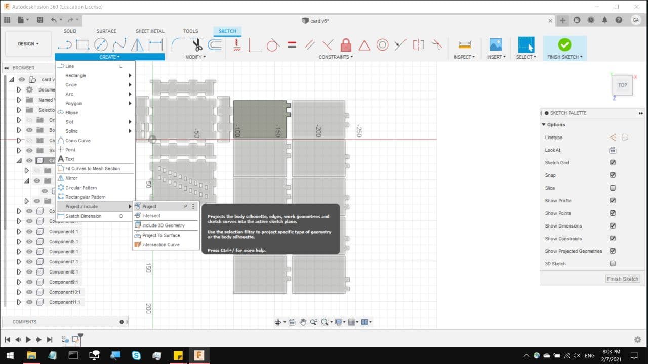
And select all of the other bodies, they should be marked with purple lines and dots,
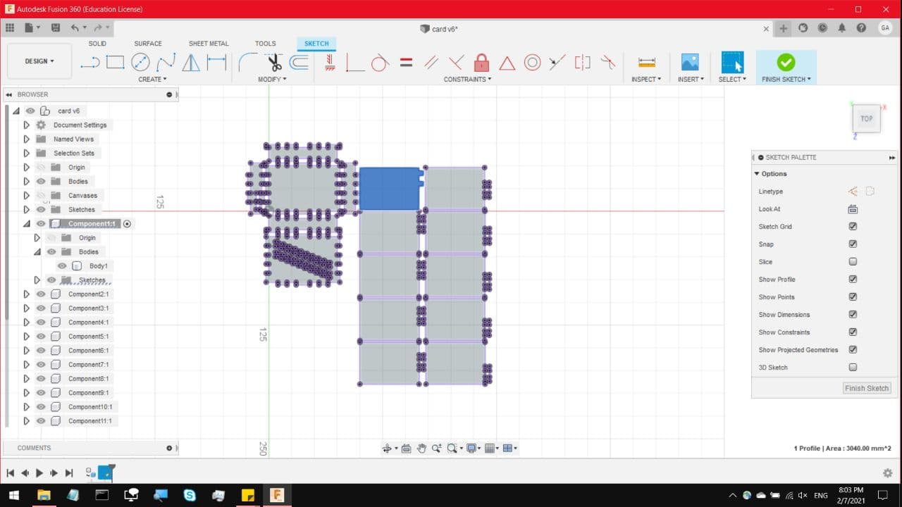
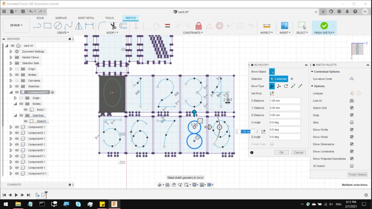
And you can add in the numbers onto each plate. Do keep track of the positioning of the notches at the bottom of
each plate.
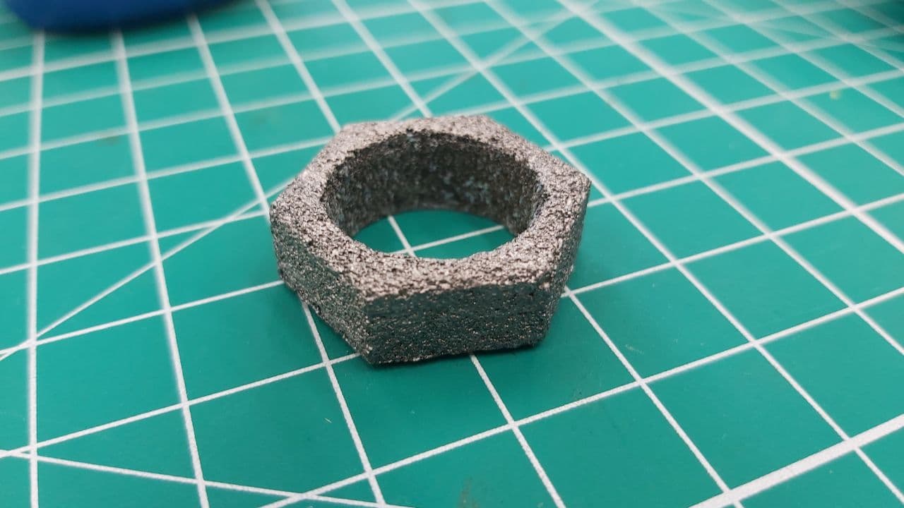
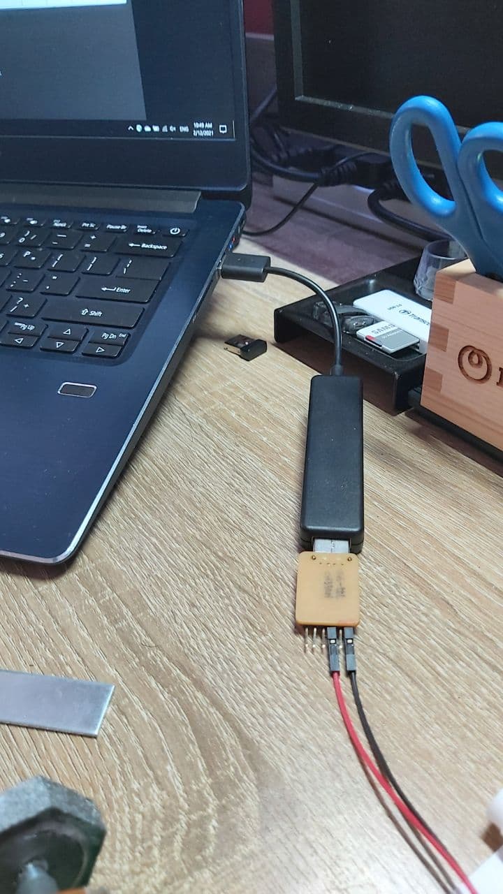
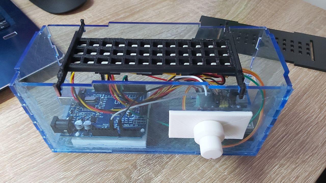
For some user interface, I built a scroll knob to adjust the speed much like last time, I ended up using the Cast nut
from earlier
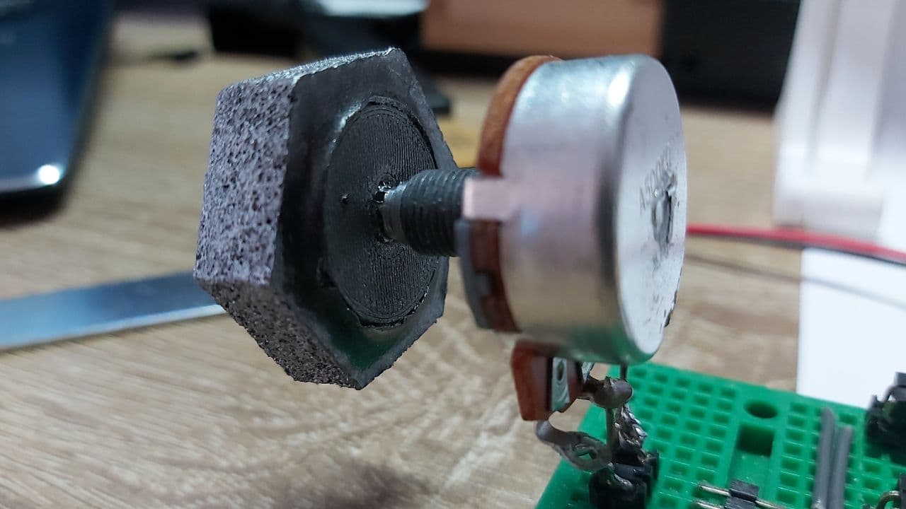
Printed a small adaptor to fit the inner ring onto the small metal knob on the variable resistor.
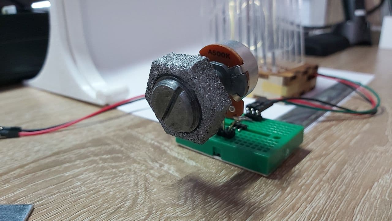
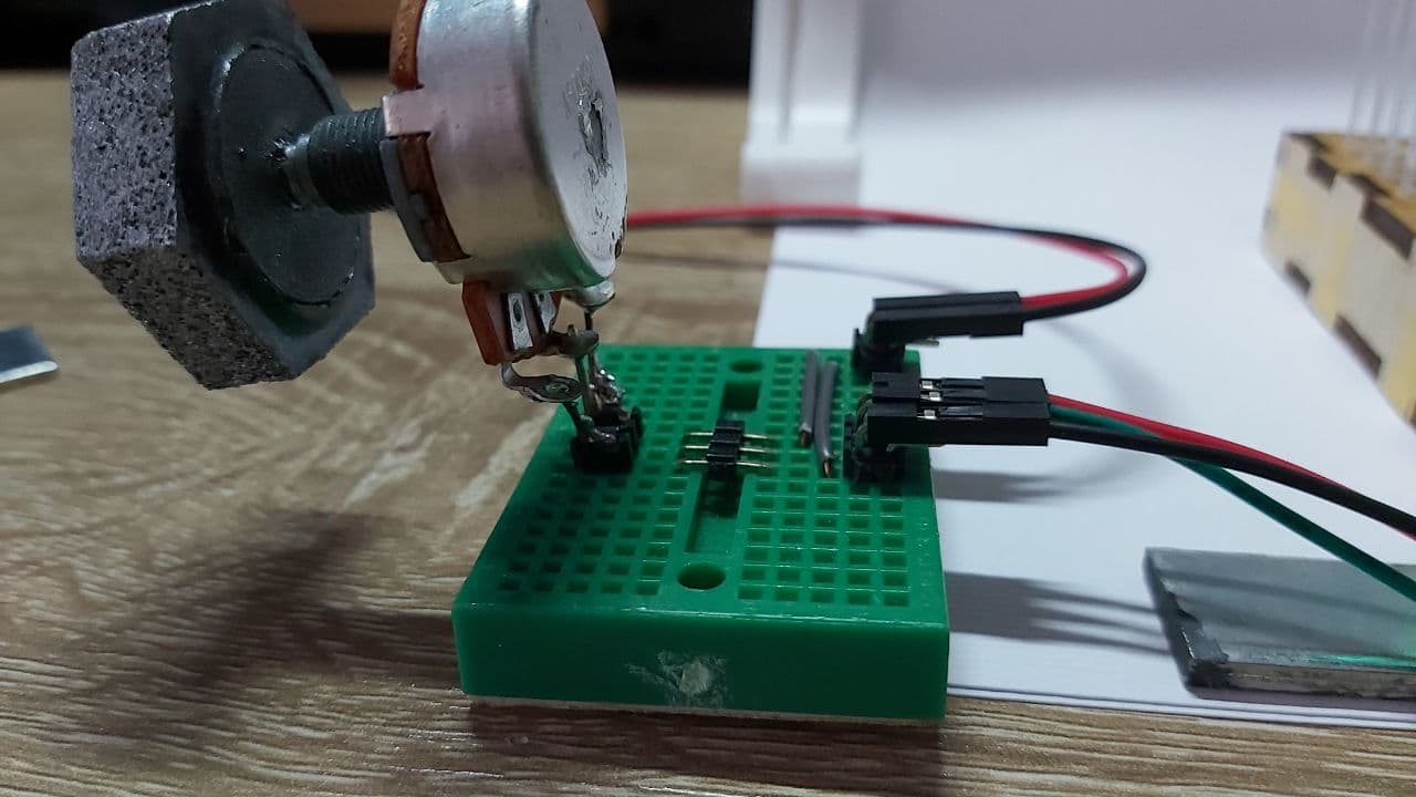
All I had to do was use my soldering iron to heat the metal knob, and gently press in the 3d printed adaptor,
And we have this set up
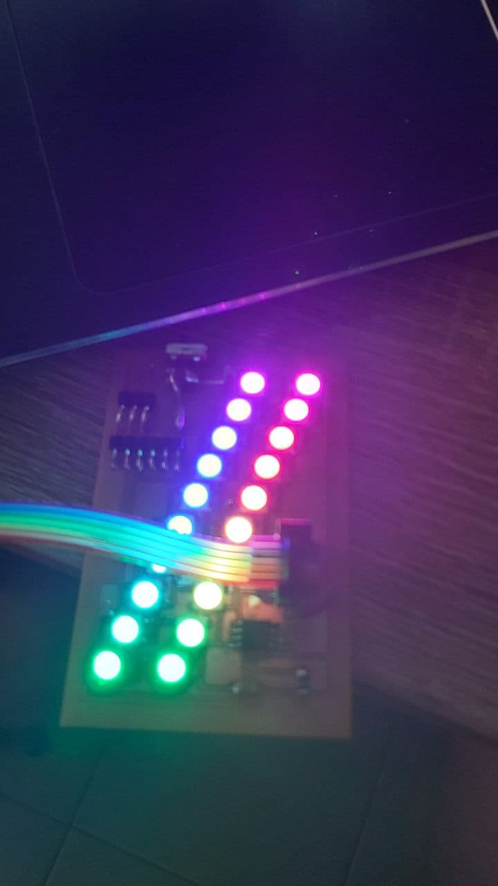
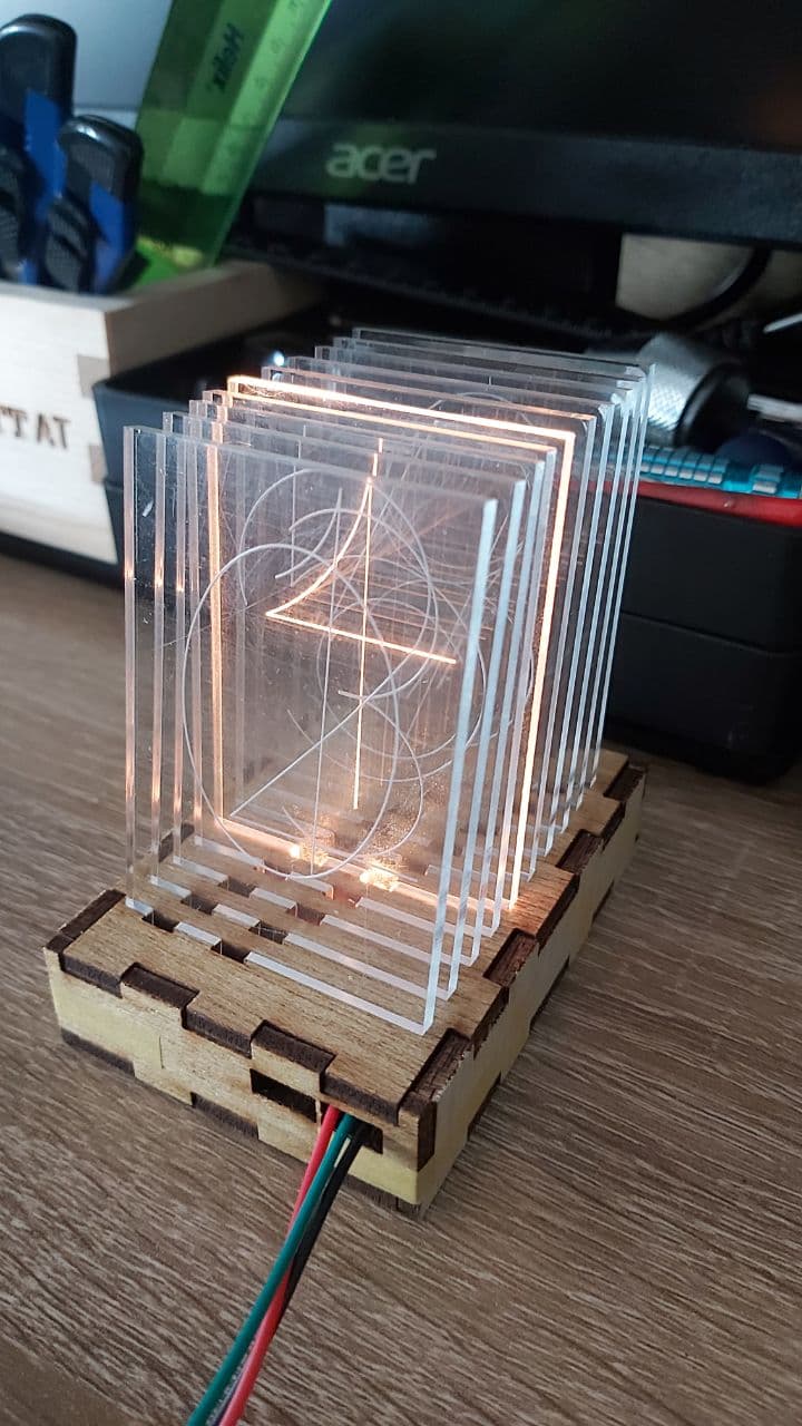
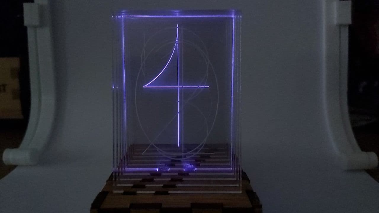
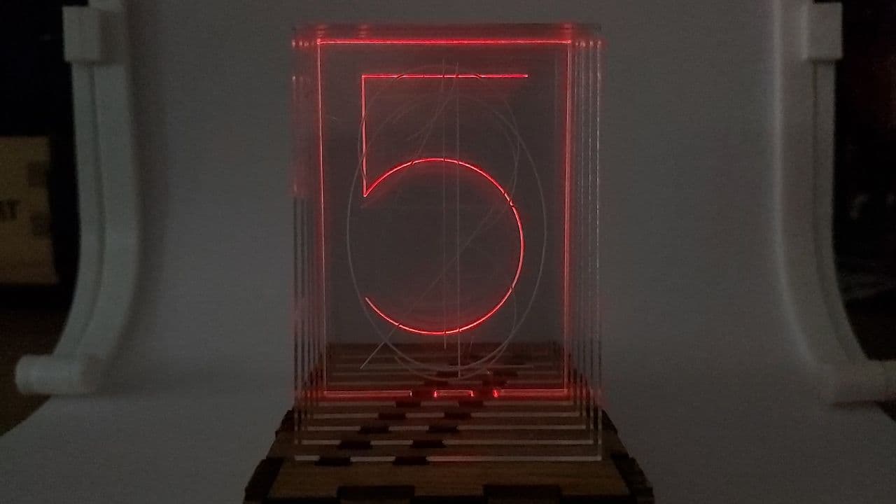
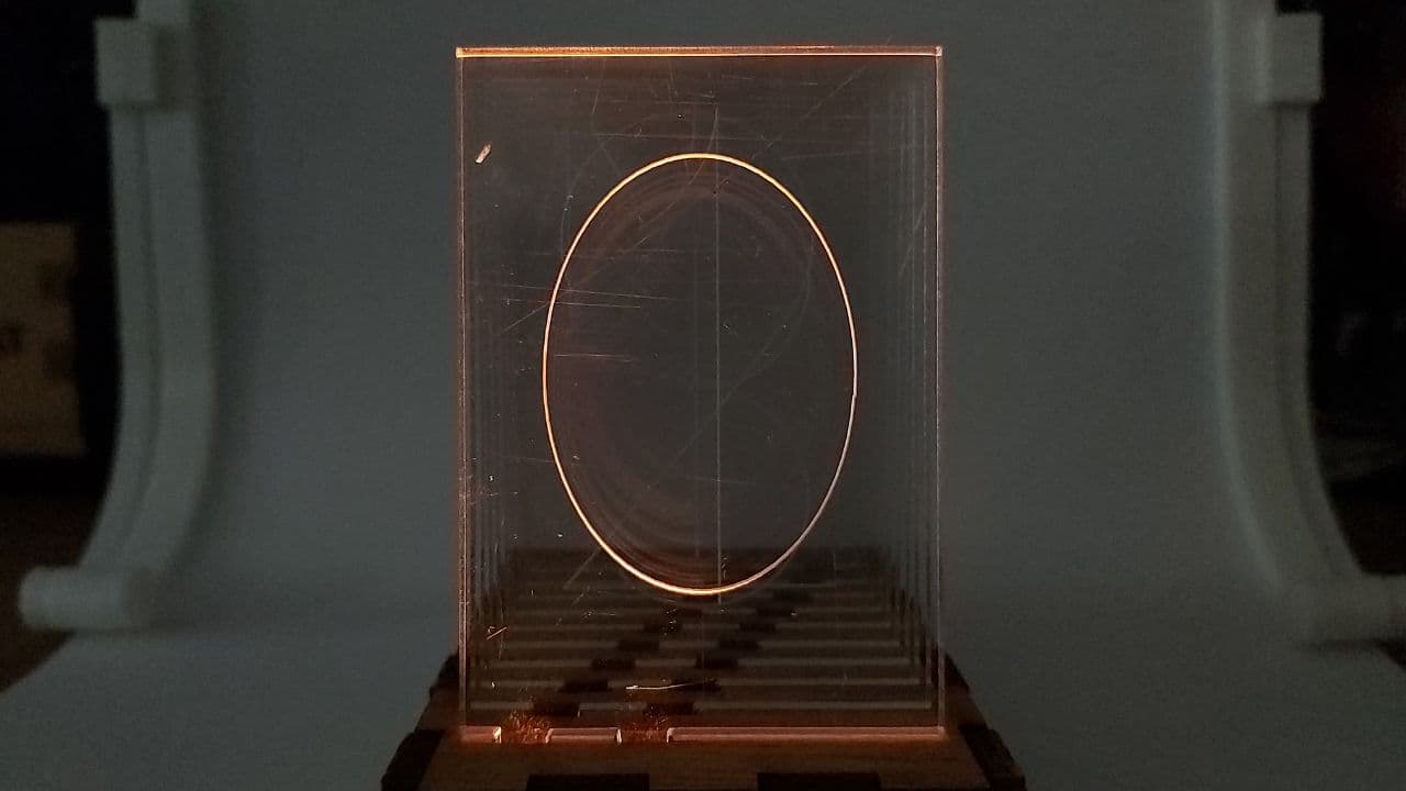
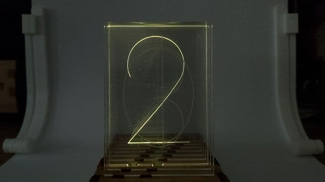
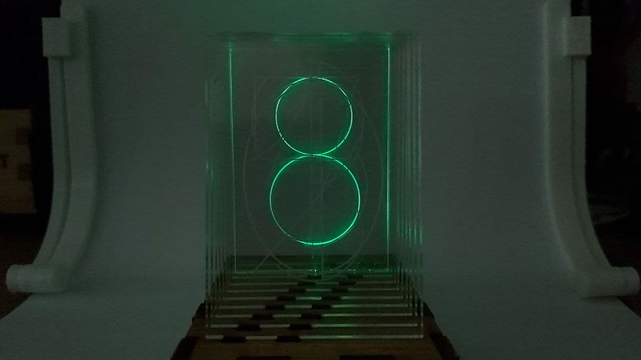
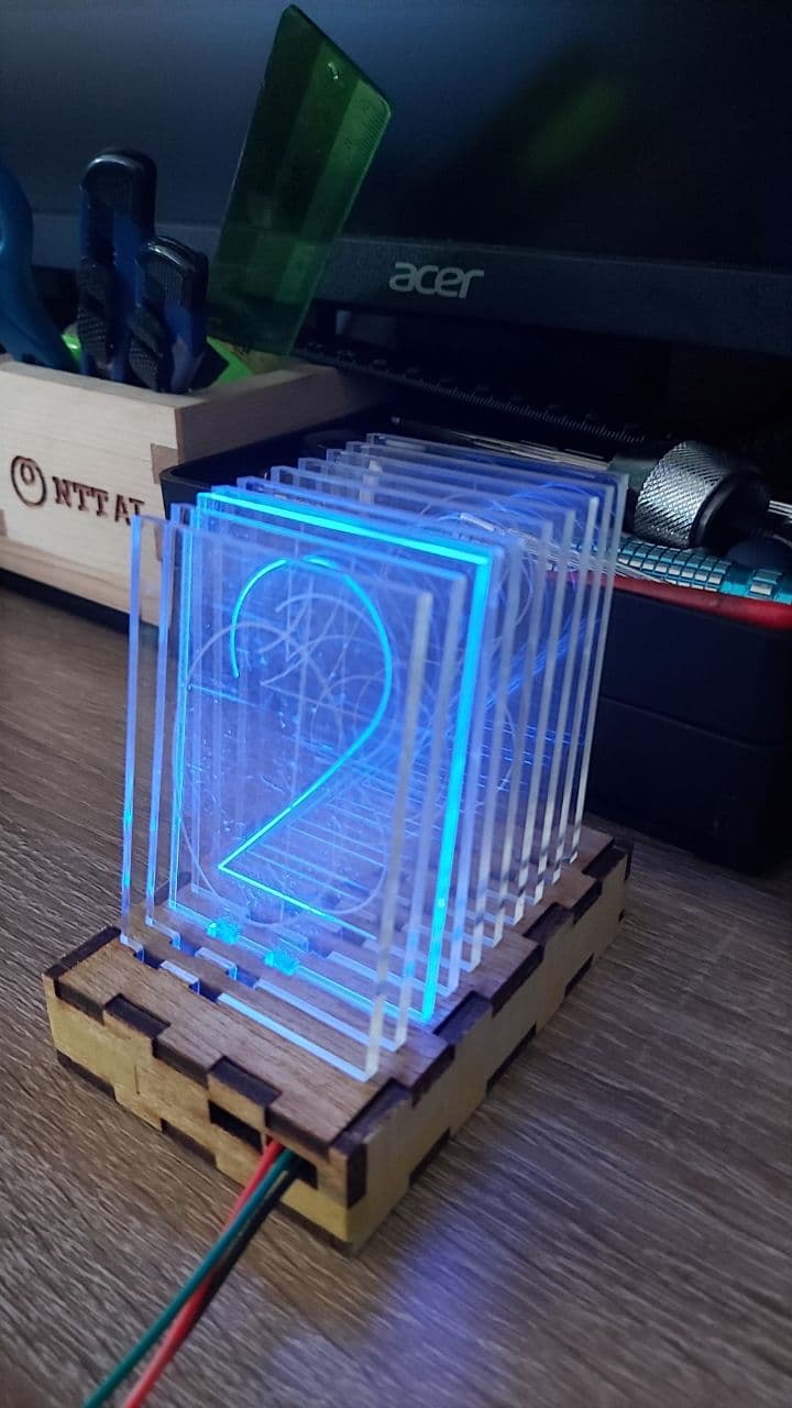
And now, while it still looks quite good in normal daylight
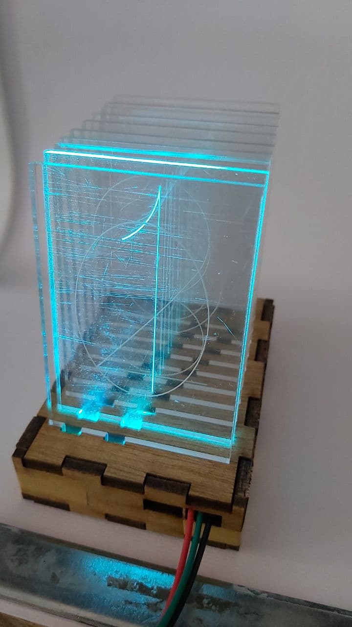
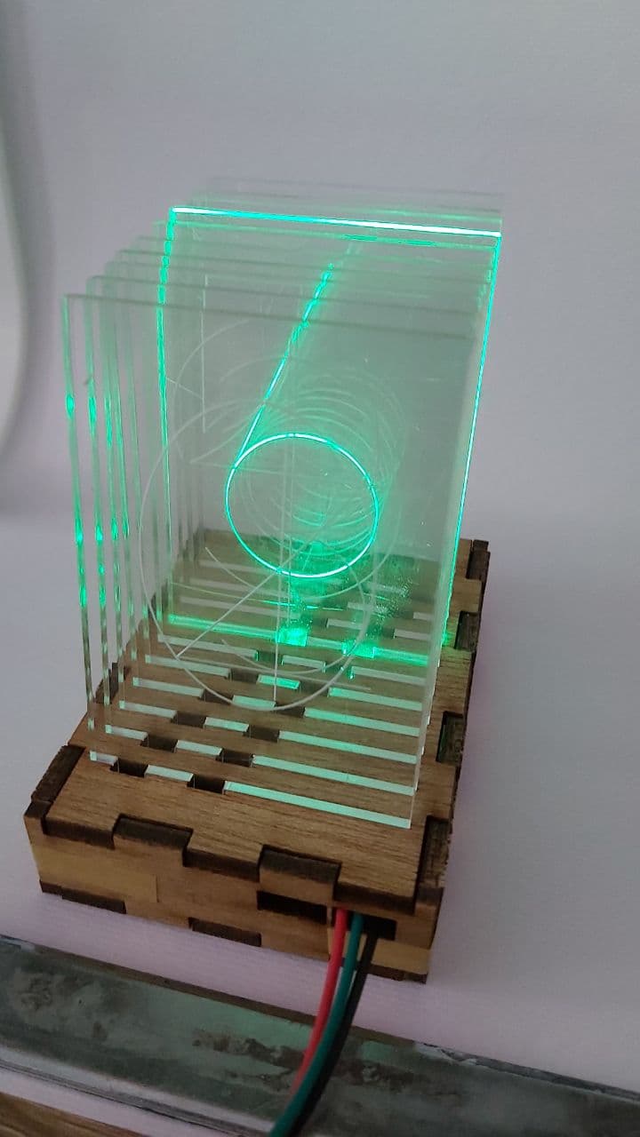
It looks even better on a white background
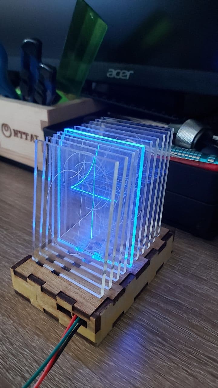
And under low lighting,
Some improvements from the original version, it can run off a 5V USB, when the previous version required 2 power supplies
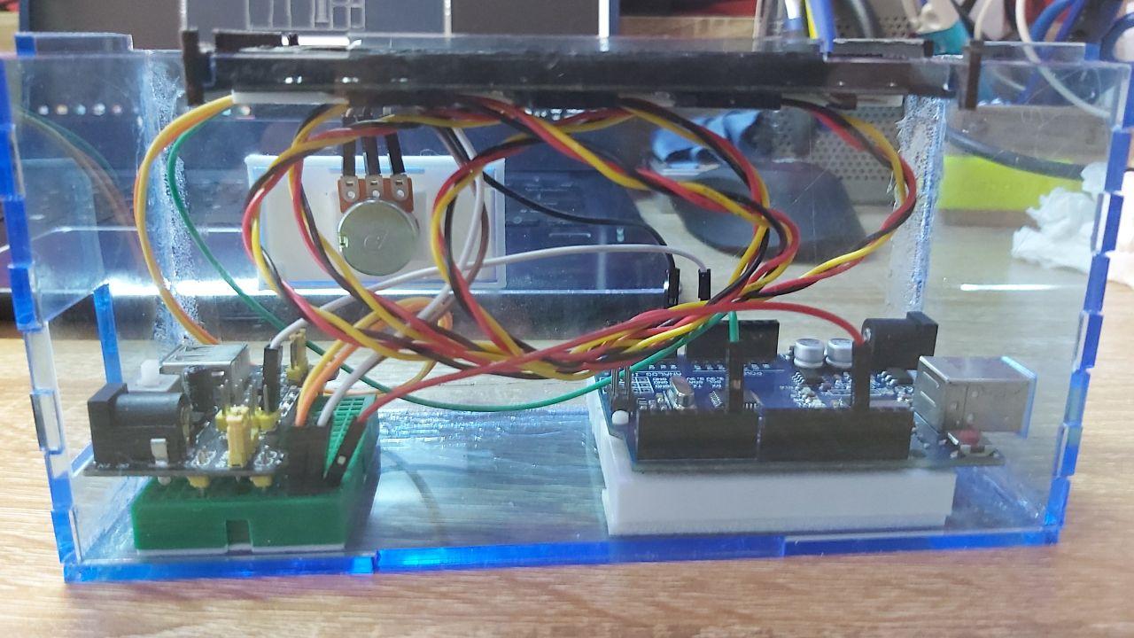
That and this new version fits on the palm of my hand, while the previous version needed to be carried in an old shoebox
As for future improvements, a big problem was the ISP pins, cutting them off in order to get the LEDs close enough to
the plates means that it cannot be reprogrammed to do other things.
Another issue was the traces, despite being cut on a single pass, they were still far too thin. That combined with the,
some of the traces being too close to an LED pad meant that a good majority of my soldering created shorts at first.
Lastly, this has also proven that my initial plan to isolate both the Microcontroller and the LED into two seperate
power supplies was entirely unneccesary, which allows me to further simplify the entire circuit.
So this is an idea of what the improved circuit should look like. First change, the ISP pinset is now a 6x1 pinset, laid
down flat, so that the board can still be reprogrammed. Second, the microcontroller and the LEDs are running on the same
power supply, straight from the ISP set at the bottom. Third, a 3x1 pinset on the lower left hand side, to allow the two
available IO pins to connect to other devices, or for a seperate microcontroller to run the Neopixels. Last, the traces
are now much wider to allow me to cut it on 2 or 3 passes, while ensuring the traces are still thick and durable enough.
Compared to the original Circuit pattern
Interfacing & Applications Programming