There are a few ways to generate Gcode for the massive 2D CNC down at FabLab, such as from Vcarve Pro.
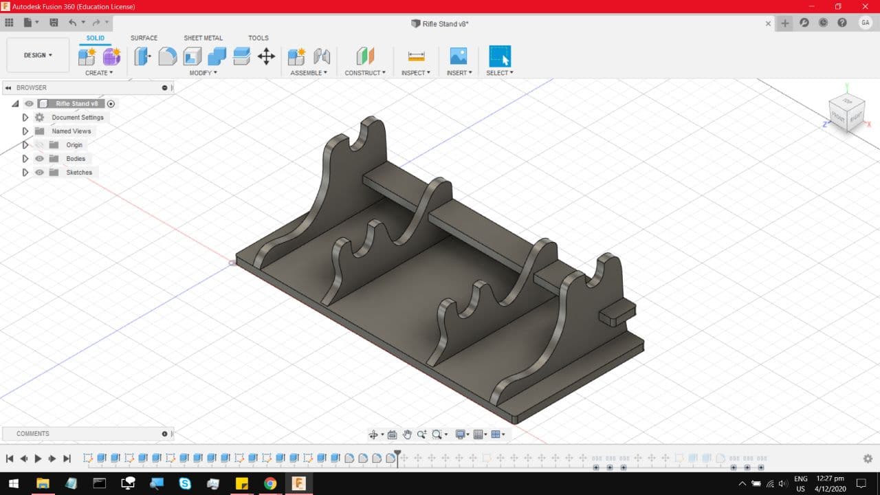
I prefer working with Fusion 360 directly. For my CNC project, I want to construct a stand for a prop
rifle and a bayonet. This is the model I built in Fusion 360, as always, link to file on the homepage.
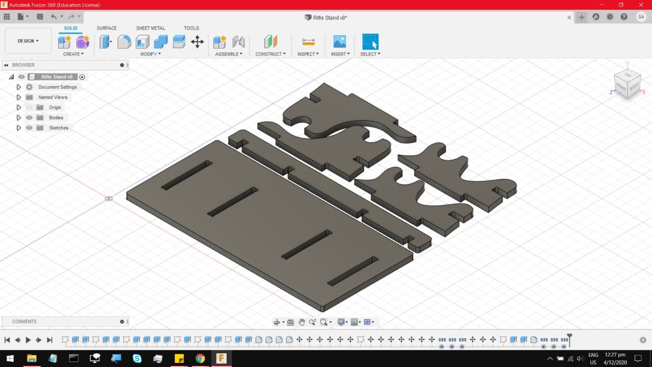
Now make sure to lay the parts flat like this
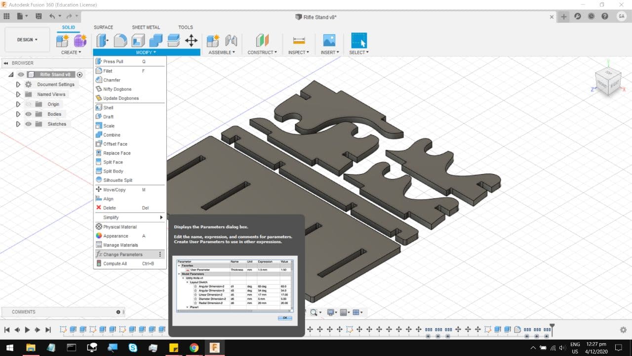
One important thing to do, is to keep all the material widths, and the slot sizes on parametric. This
makes it much easier to edit the model to account for inconsistencies in the material thickness.
Under modify, change parameters.
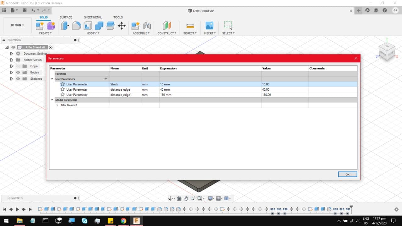
You will arrive at this menu, notice that the material thickness I selected is 15mm, which is the typical
thickness on most of the scrap plywood sheets.
Also, because the CNC machine uses a rotary bit, it does not cope well with Right angle cuts. Which is why
we apply these cuts known as Dogbones into the right angle cuts. Without them, the Right angle cuts come out
with a small fillet because of the rotary bit. I am using a dogbone Add in I found on the Autodesk app store.
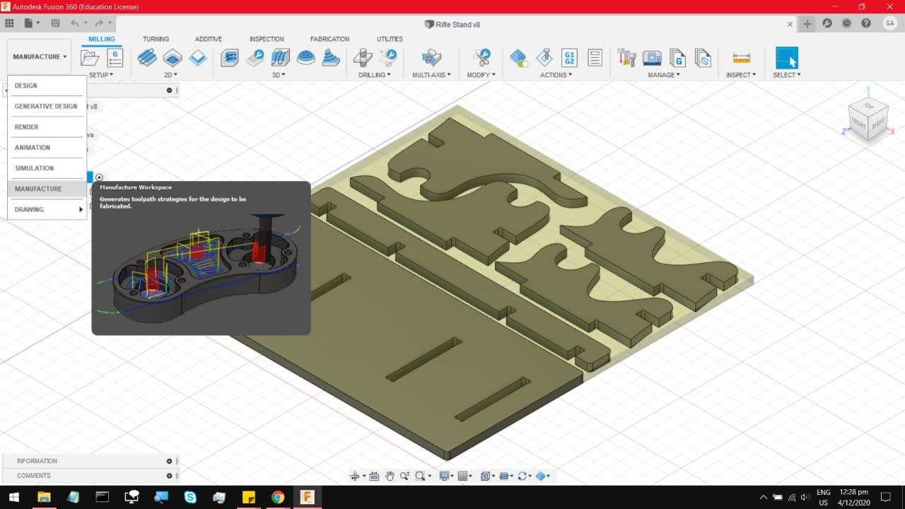
Now on the top Left, switch the mode to Manufacture.
Under Setup, select New Setup.
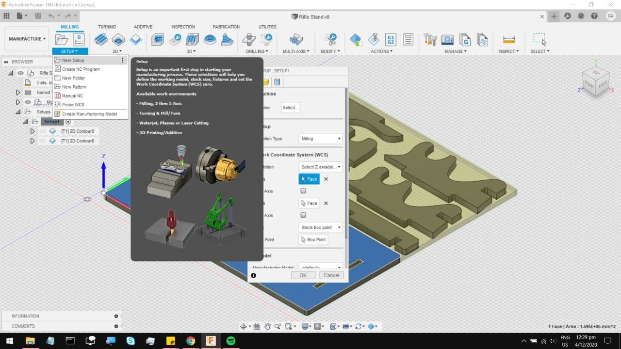
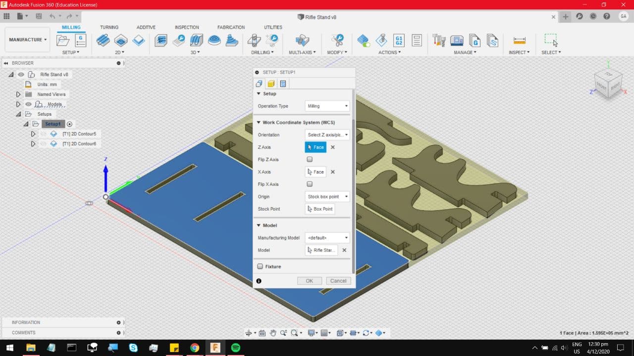
You will arrive at this menu, and under Setup, make sure your operation type is Milling. Under Work
Coordinate System, follow those settings and make sure your XYZ marker is on one of your corners, with
the Z marker facing up. The idea being that Negative Z means cutting into the material.
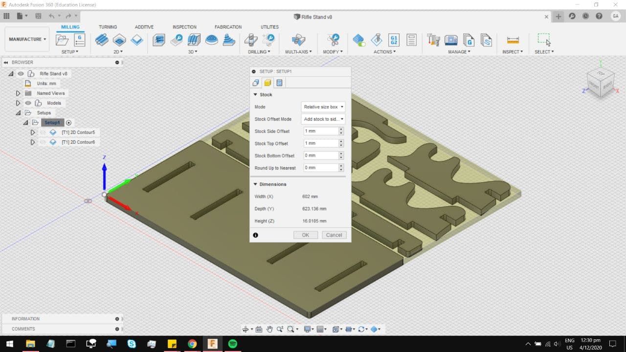
On the next tab, follow those perameters. You can even see just how much material you need. For this
project I estimate that it will take up about one quarter of the fresh stock.
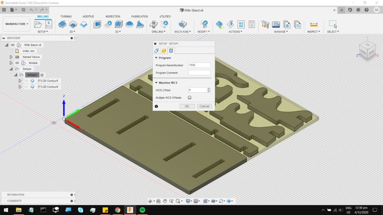
On the last tab, you can select a job name, and hit OK.
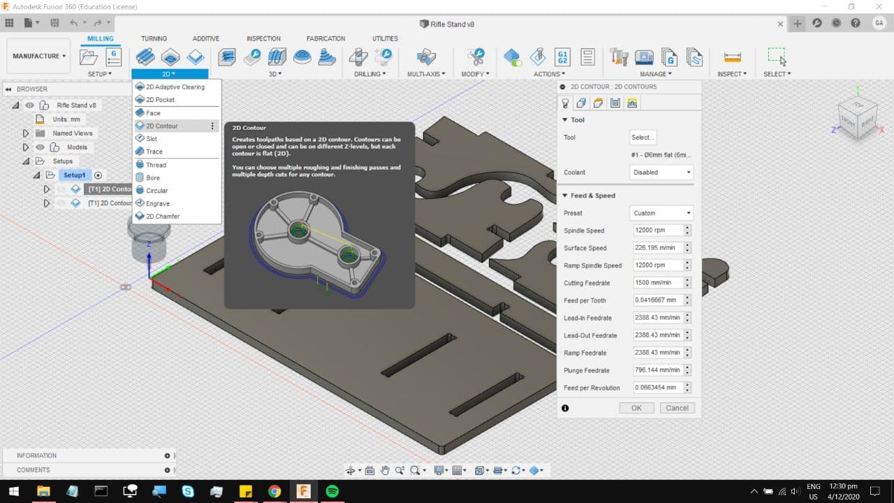
Now our first process would be to cut the slots out of the base, its easier to cut those out before cutting
the entire section out. Under 2D, select 2D contour, which allows for complete cuts through the material.
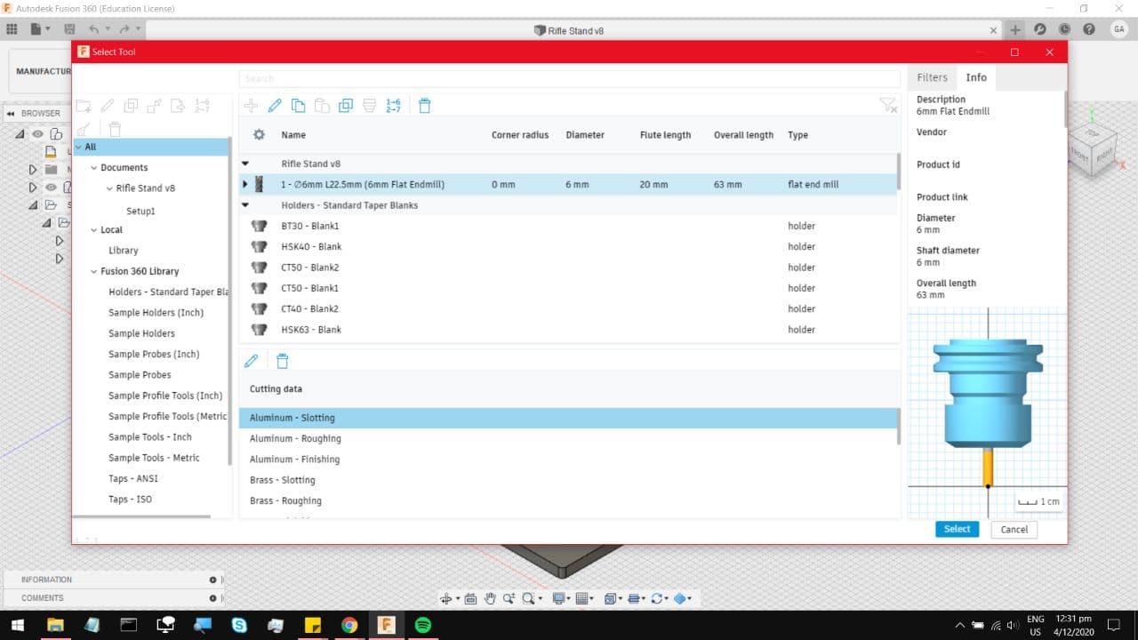
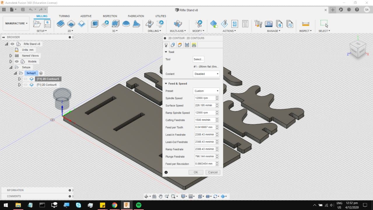
On the first tab, under tool, click select and you will be brought to this menu. The tool in the FabLab is a 6mm
Flat End mill, running an upcut. Much like milling out the PCBs in the previous section, you have to take multiple
passes when cutting through the material, otherwise you risk sheering the mill bit off, which is quite terrifying.
This also means that the cut finish on Plywood is not as clean when cutting against the grain on the top layers.
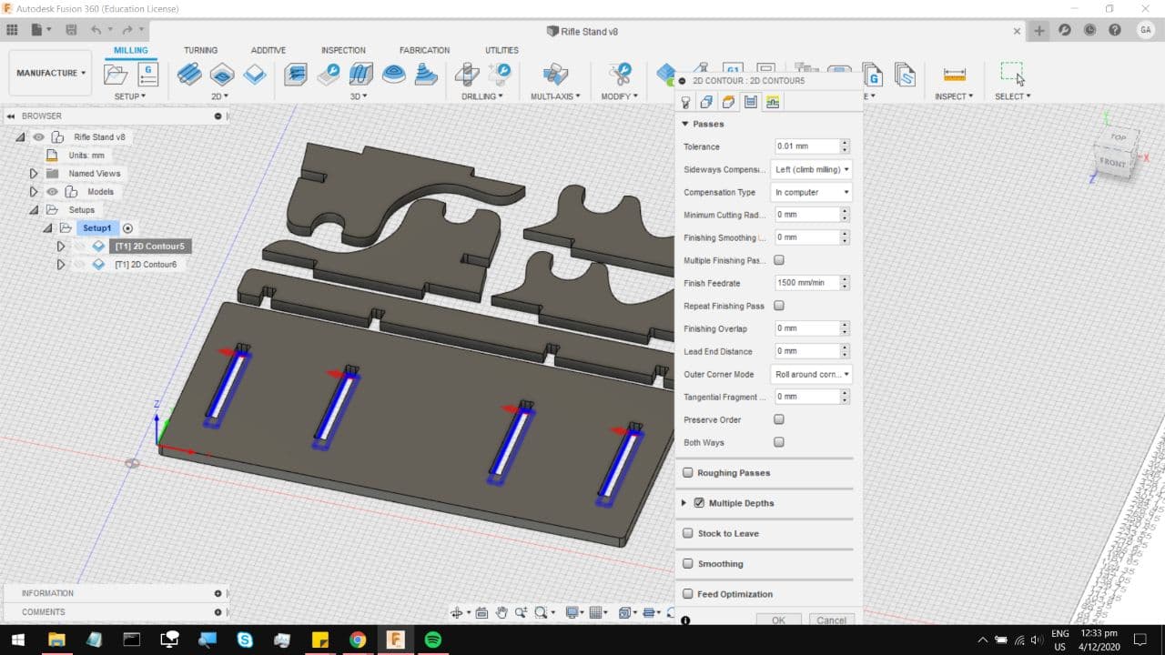
Now those are the parameters I am using for the cut. The main concern is the Feed Rate, in other words how fast the
mill bit is getting dragged through the material. On the PCB millbit we used something around 50mm/minute, this one
can take around 1500mm/min. I am not too confident with this feedrate so I might end up going into the text file and
changing the number to something a little slower. As for Coolant and Spindle Speed, the machine down at FabLab has the
spindle speed controlled externally, so your Gcode would not change anything, and it doesnt have active coolant either.
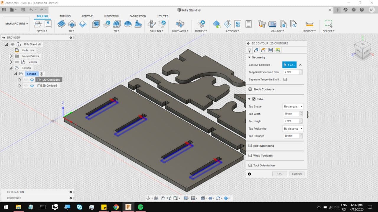
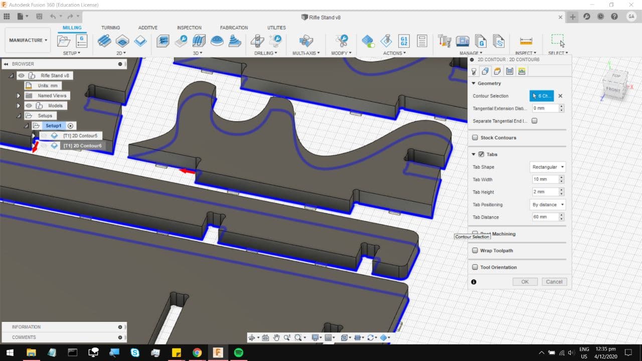
On the next tab, select the lower profiles of the slots you want to cut. This tells the machine to cut to the Lower depth.
Also, select tabs as there will be a small piece of leftover wood in the middle of that slot cut, which might get flung
around and possibly damage the rest of the wood. I tend to keep the tabs at around 10mm by 2mm big, and select them by
distance. You can go in and manually place the tabs by changing the Tab Position setting. But on a model this big, I am
perfectly fine with hammering out many tabs.
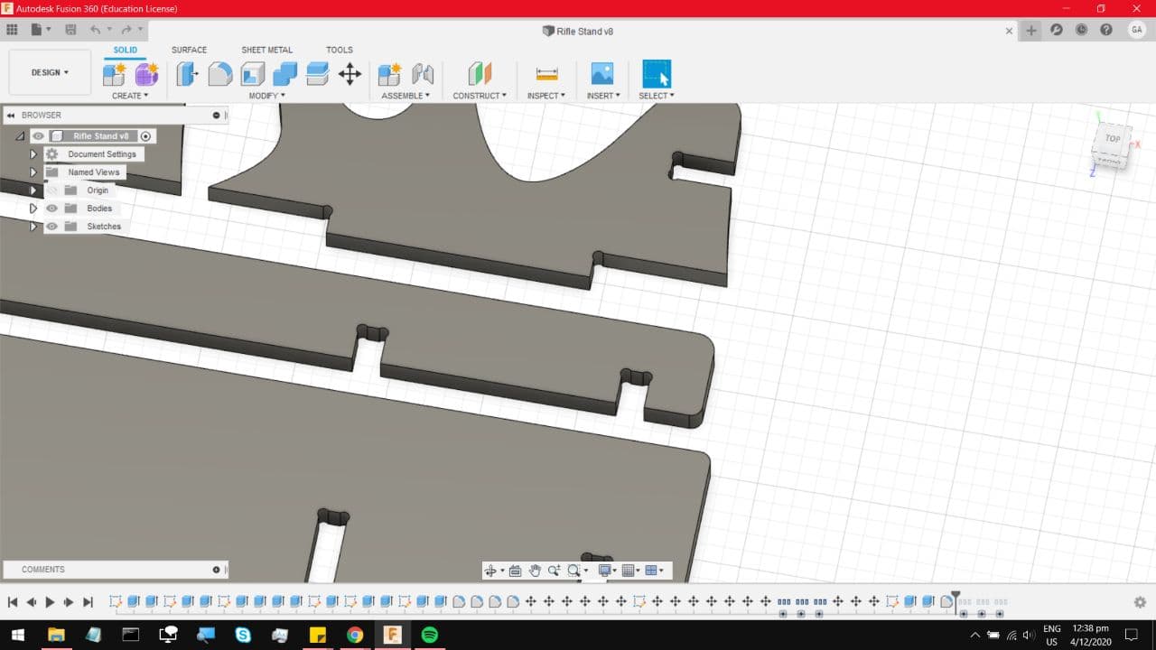
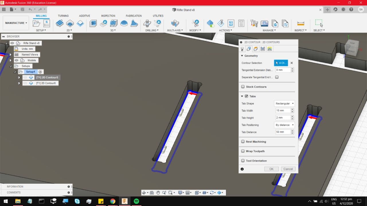
If you zoom in you can see roughly where the tab will be made. In some cases if you choose to set tabs by Distance and not
manually, it will assign tabs in random locations. But on closed profiles like that slot, it manages to keep the position fairly
symmetrical.
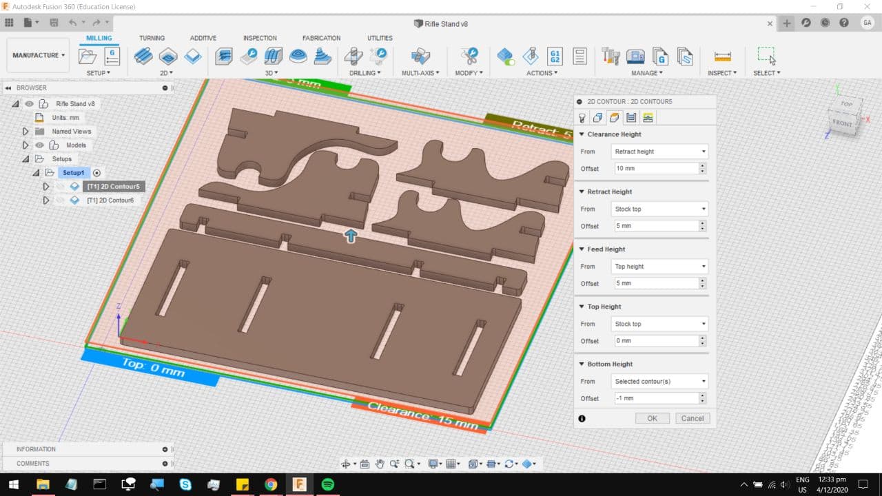
On the third tab you can keep to the system defaults, all except for the bottom height which is offset by -1mm. This
ensures that the mill bit punches clean through the material, and makes the finish slightly better on the bottom surface.
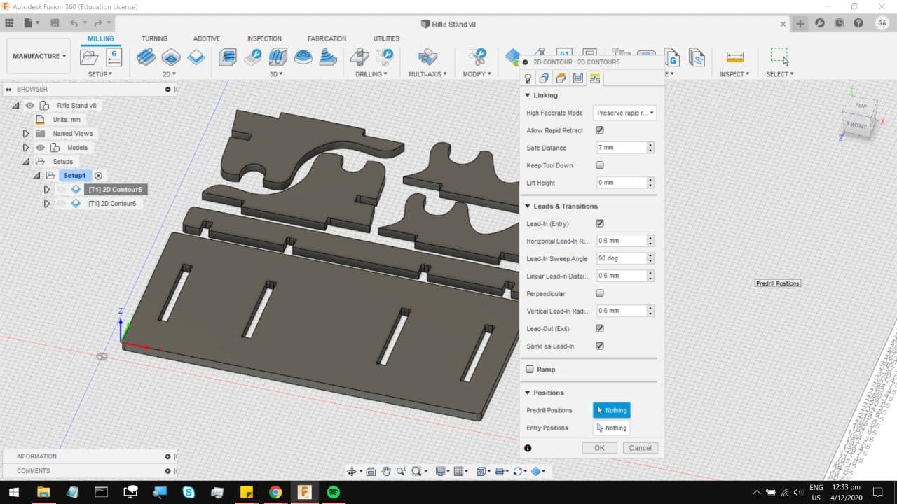
Now on to the fourth tab, you can keep to the same default settings,
Select Multiple passes, choose your roughing stepdown to somewhere around 6mm, and you can leave finishing stepdowns to 0,
at the end the cut finish will still look quite rough, so you can select rough final. After all, sandpaper solves everything.

On the last tab, you can keep to the default settings and hit OK.
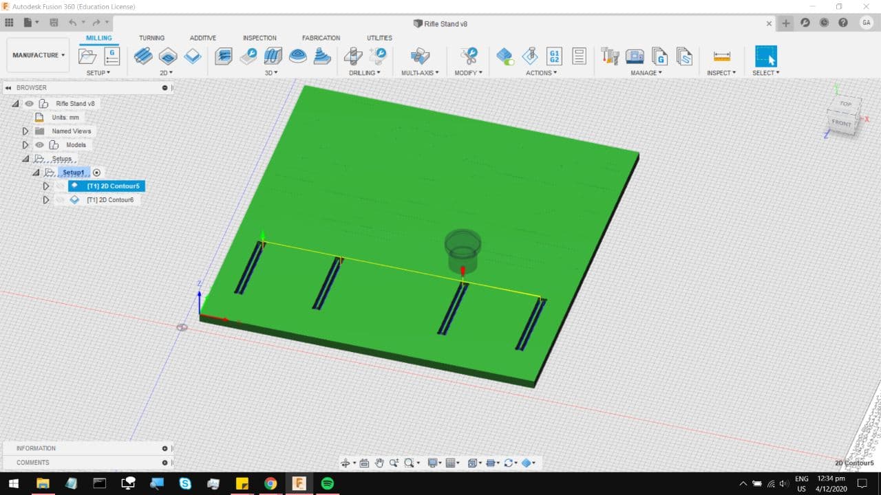
Which leaves you with this cut profile where you can press simulate under actions, and check if it really is doing multiple passes.
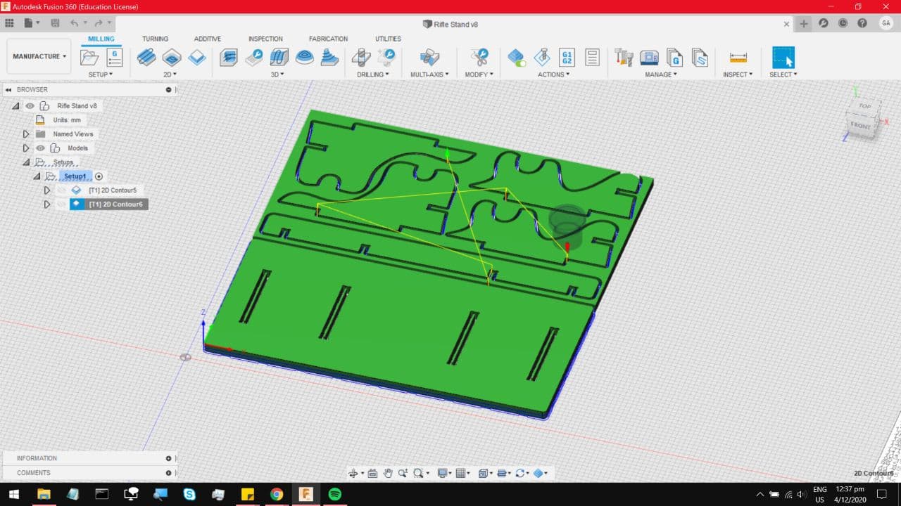
Now, repeat that exact same process for the rest of the cut, remember to select the lower profile, so it cuts to around
that depth. You can keep the exact same parameters, multiple passes at 6mm stepdown. The only difference being the tabs.
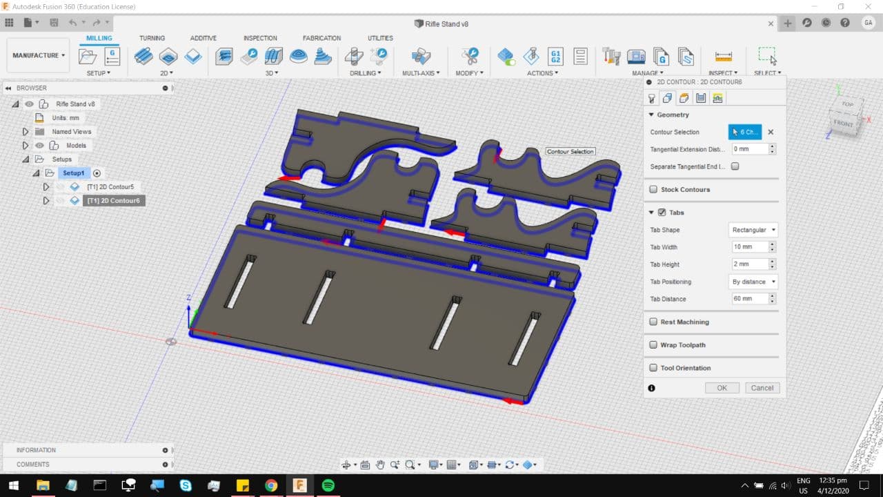
Notice that now fusion 360 decides to throw tabs in random places, which you can change around by increasing the
distance between each tab, or simply just setting each tab down manually.
Which leaves us with this final cut profile. You can move the order of the cut operations around, to ensure some cut operations
happen before others, again simulate to make sure the GCode is actually taking multiple passes, and doing what you need it to.
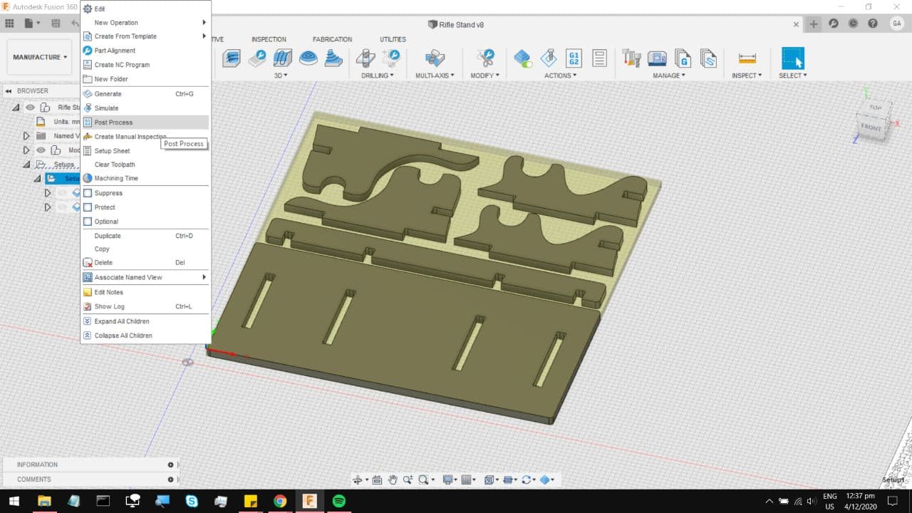
Moving on to Post Processing, Right click on your set up, and select post processing
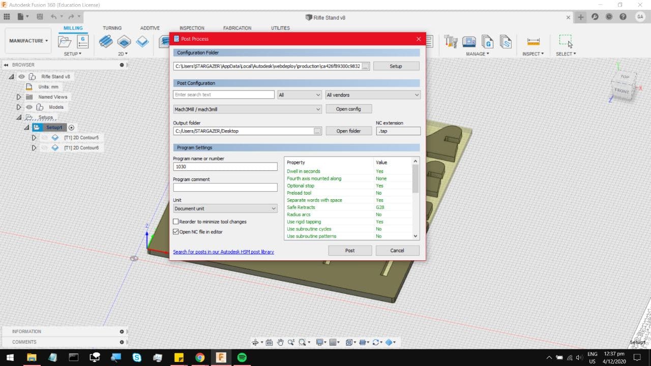
Which brings you to this page, select Post Configuration, and choose Mach3mil for the FabLab CNC, which throws in all the necessary
additional code and indentations. Choose the file output location to somewhere easy to get to like your desktop, and hit Post.
For an additional check you can take it to either NC viewer or Camotics, either will do. Now, time for the machine.
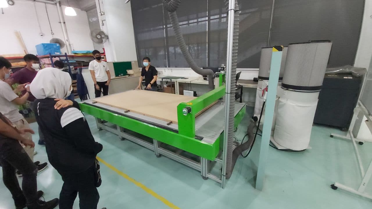
You cannot operate this machine without a technician around, and frankly that is a good thing. This is the spindle head
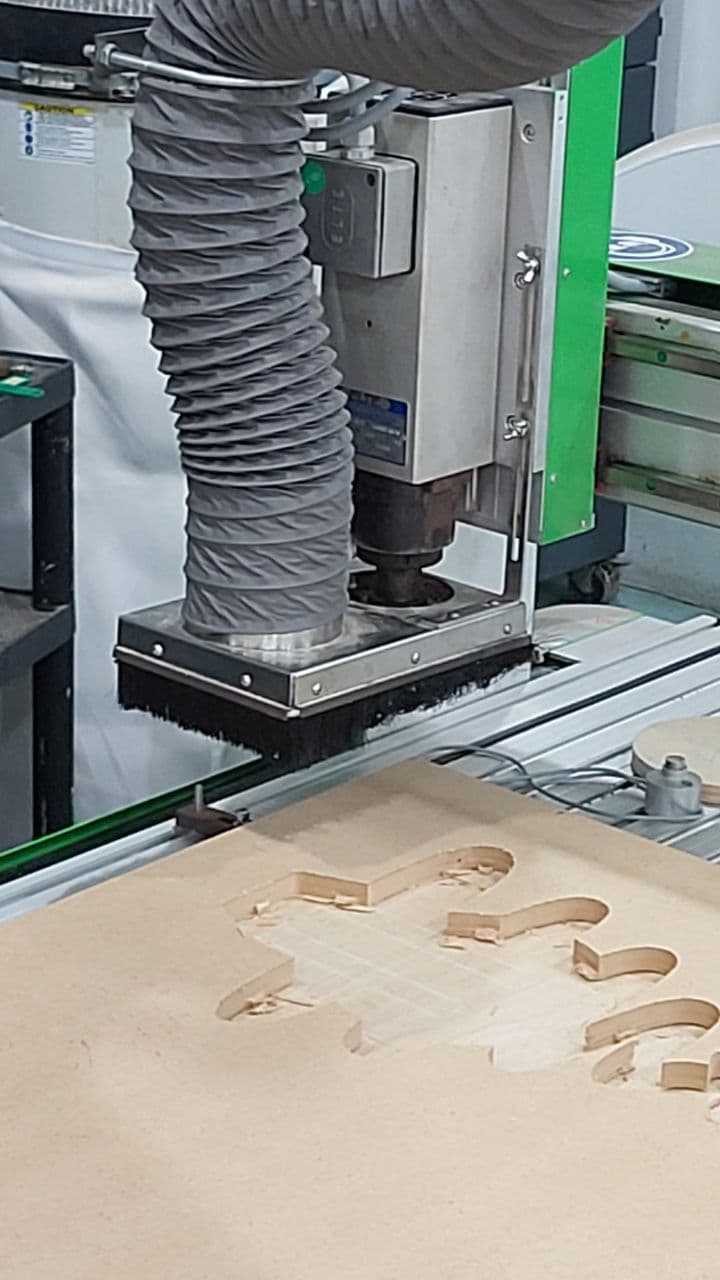
And much like the PCB milling machine, this also has a Z calibrator. You can put it on another piece of wood when calibrating
if you want to run an Air Cut first.
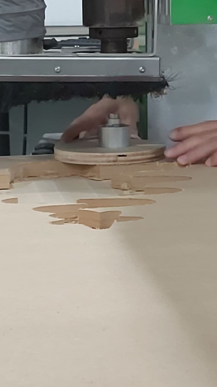
The first thing we did was to run a sample cut, to see how well the machine handles 15mm plywood, with a pocket and a slot.
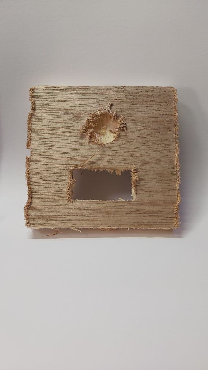
Overall, the end finish is not terrible, which you can fix with a penknife and some sandpaper. Notice how the burrs
and the splintering occurs more around the edges where the bit is running against the grain of the wood. It was great
fun carrying this thing home on the train and have little bits of debris fall off everytime I shook it around. But this
does serve as a good warning for when I cut out my rifle stand: bring an Ikea bag.
Its been a few months, and I have finally managed to cut the Rifle stand model, and its time for the cleanup process.
First was to bring it somewhere open, where dust was not gonna be a problem, such as a staircase.
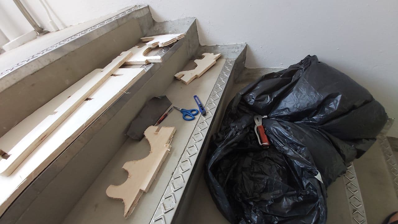
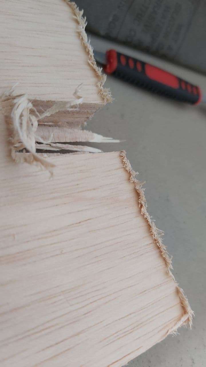
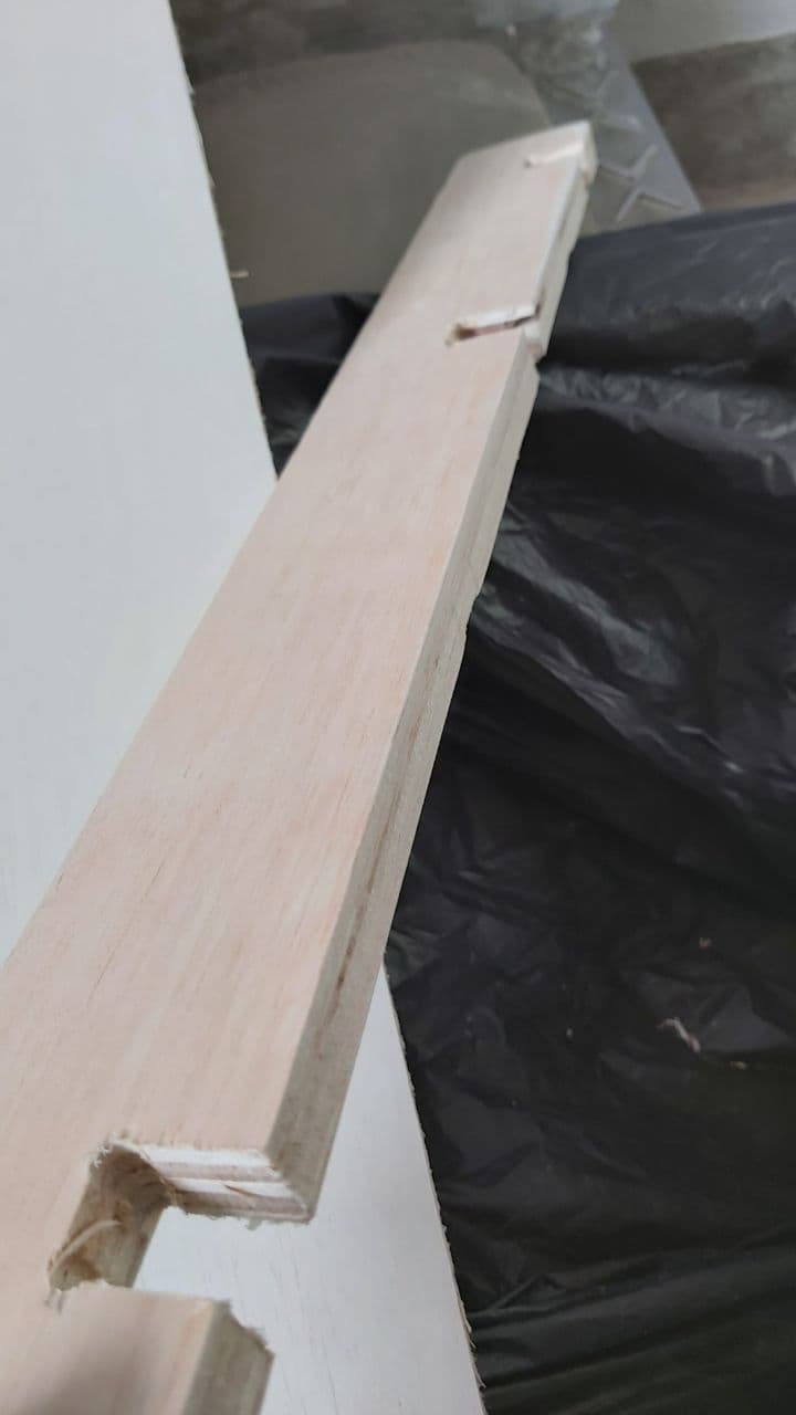
The main issue are these burrs, which is a result of a slightly dulled out endmill bit, but nothing a penknife cannot fix.
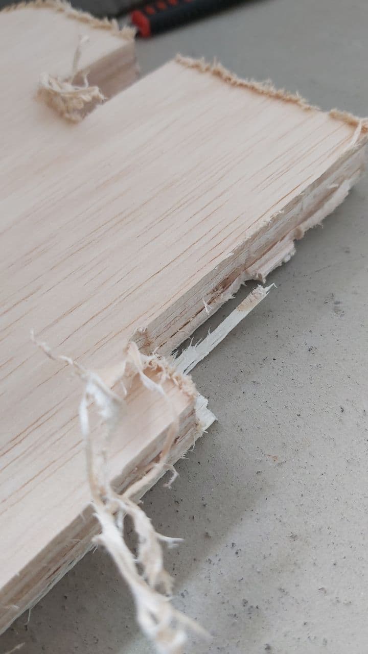
These usually occur where the endmill was cutting against the grain on the outer layers, which meant that
it was easy to predict which surfaces would have these burrs,
Once that was done, the pieces looked alot neater, which allowed me to take these to some coarse sandpaper.
The wind really made appreciate wearing a mask.
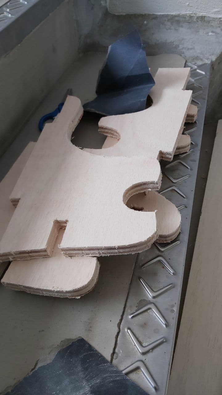
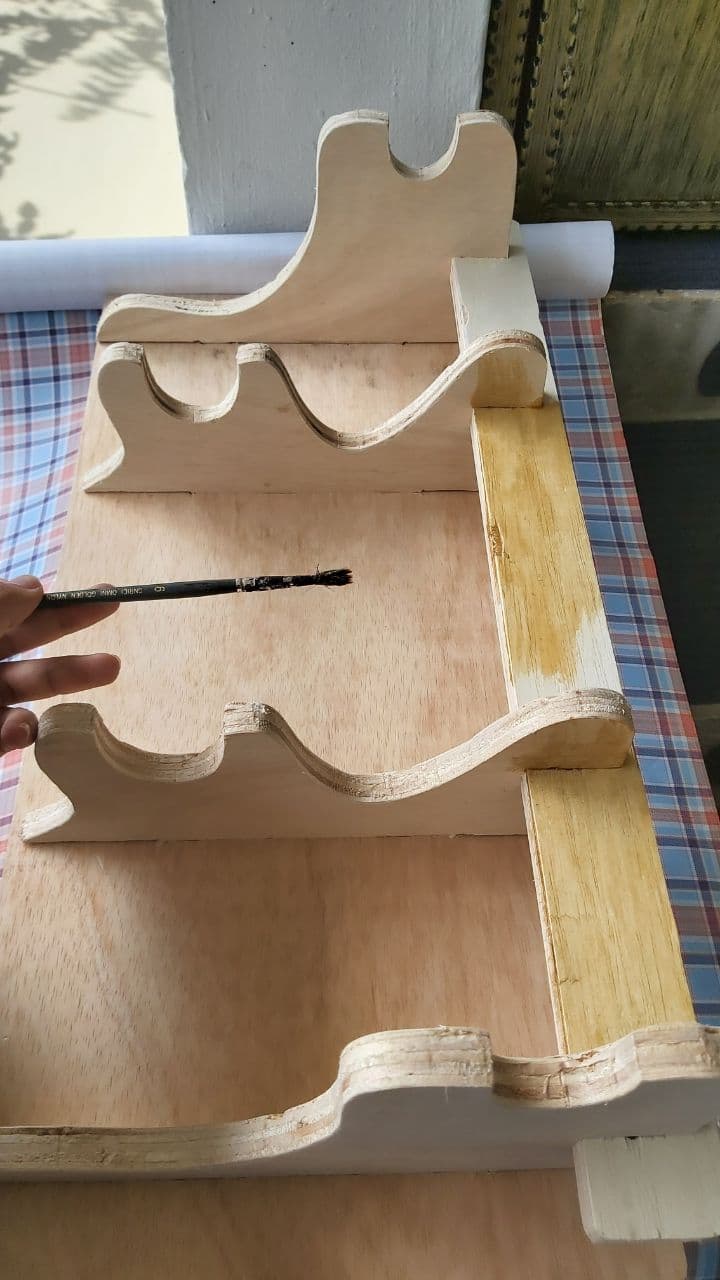
And here is one of the pieces sanded down, you should at the end be able to lightly glide your finger over the surface,
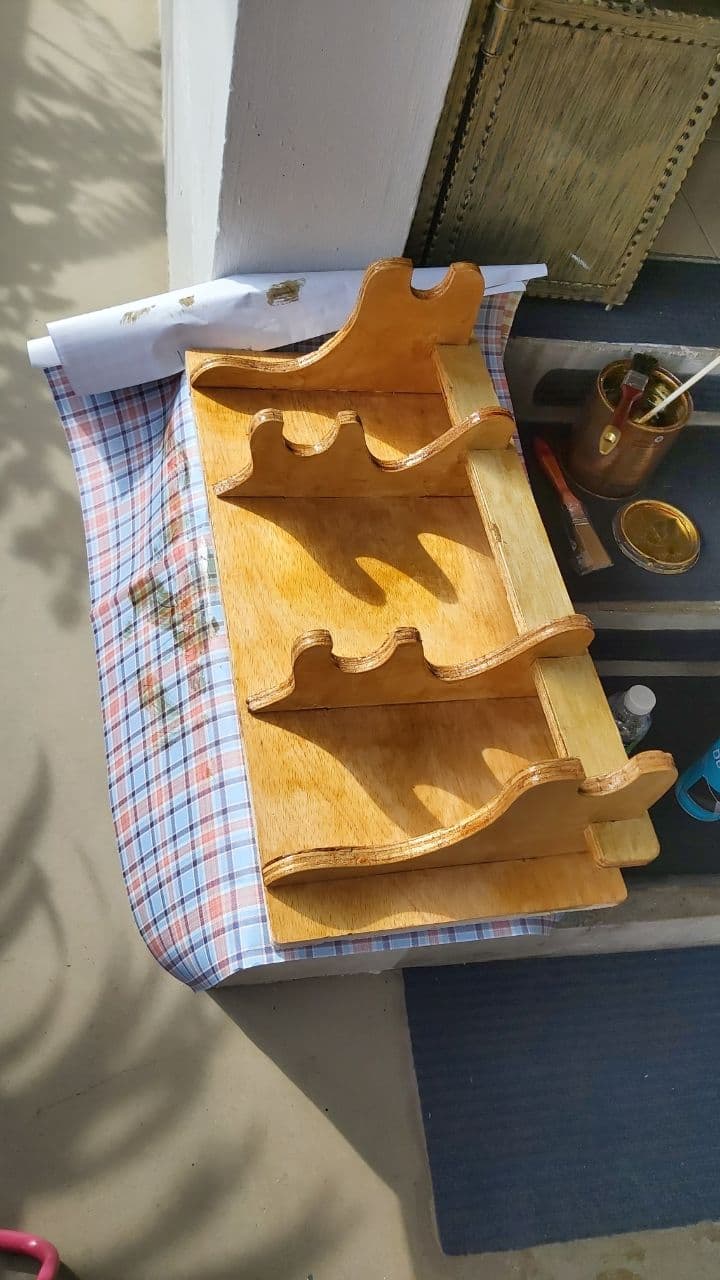
Its took some sanding, and some minor cuts with a hacksaw to get the tabs to fit, but in the end it required No glue
After the press fit, a coat of varnish really made the colours pop.
Interfacing & Applications Programming