Given that one of the problems with the last project was the fact that I had
to build the entire project around an LED board that someone else had designed.
This leads to the first topic, Making our own PCBs, so that we can work on Our
design parameters, without having to resort to questionable Hand-fitting methods.
There are many ways we can produce our own PCBs, such as etching by Ferric Chloride,
or by film lithography. Those can produce some very high quality PCBs, but they come
with their own issues like waste chemical disposal, and more importantly, the Cost.
Which is why the method we will be using is by milling/machining. In short it involves
a CNC router with a very fine bit, cutting away a pattern from a thin sheet of copper,
which is laminated to a sheet of something non conductive like plastic, as seen here:
Easier said than done.. first we need to generate a Gcode file, but we'll cover that later on.
In order to operate the router, we need to upload our Gcode file, which is just a set of
Machine operation instructions, and several hundred coordinate instructions in relative XYZ.
The specific CNC device we have access to is a modified Stepcraft 420, as seen here:
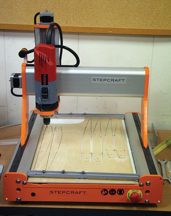
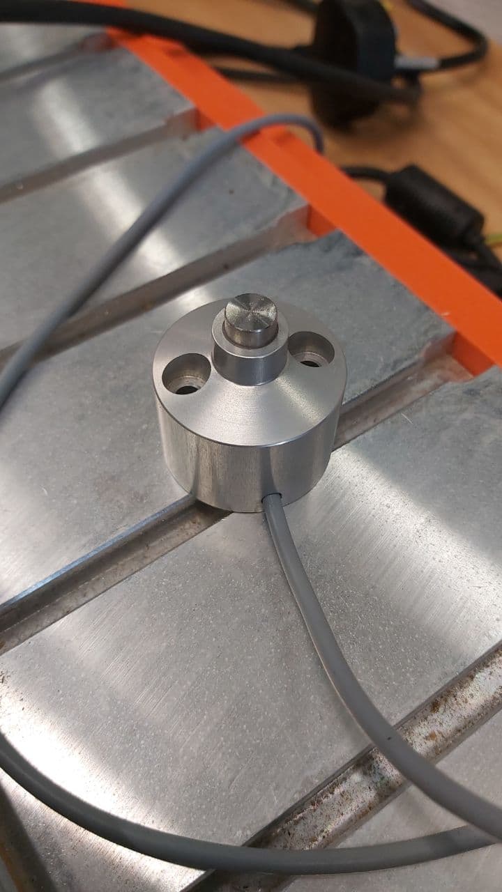
You'll notice a small silver cylinder on the back on a wire, that is the calibration device for
the miller. The device might require some calibration before running it, so here are the steps.
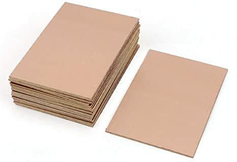
First, go get a copper blank, which looks like this, apply some double sided tape to the back, and paste
it onto one of the cutouts in the plywood bed. Be sure not to overlap any of the double sided tape, you
need to keep the copper blank as level as possible. For some added security, get some masking tape and
tape the sides of the copper blank down to the bed, to keep it from slipping off the plywood.
Now grab a spanner to open the chuck of the mill head, there is a black oval button somwhere below the main Start
button, pressing that will lock the rotary head of the mill in place, allowing you to loosen the chuck on the mill.
Open it up, and slip in your mill bit. Now there are 2 main types, V bits, and straight End-mills. For cutting traces
I would recommend using a V bit as it is much more stable, and you can control the Width of the cut purely based on
the cut depth. Save the End-mills for cutting out the outline of your board. Both of them are equally sharp and fragile
so pay attention, and take your time when securing the bit into the chuck. Try not to overtighten the chuck, but also
try not to leave it too loose. The moment turning the spanner becomes significantly harder, that's the cue to stop.
For context, these are V bits, most in the box will still be fairly sharp.

And these are End-mills, you'll notice that a few of them are not as long as the others, those were
probably broken off during milling, high torque and a very thin bit are not a good combination.

Now place the calibration device onto the copper blank, and manually guide the router head to the calibrator
using the arrow keys for x and y movement, page up and page down for z movement. Press shift to increase the
speed of the movement, but do not press shift too often or when the mill bit is anywhere near the bed. There
is a chance that the computer will sense and lock Sticky Keys while you're moving the millbit up and down, and
instead decide to crush the millbit into the workpiece you spent 40 minutes waiting for. Slow and Steady is key.
Look to the computer next to it, and you'll see this UI, to load in your Gcode, select Toolpath and Load file.
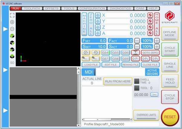
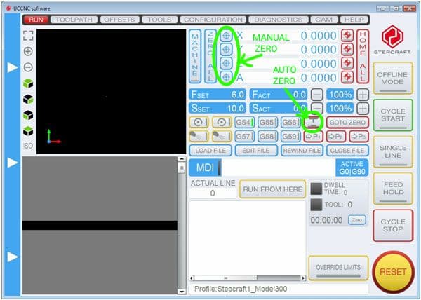
The highlighted button here will lower the drillbit onto the calibrator to re-zero the new Z height.
Press that button when you have the Gcode ready to run. It is recommended to do an aircut beforehand
to see if the miller is tracing out the approximate correct pathway. To do the aircut, manually set
the Z height to a zero slightly above the copper blank, and hit Cycle Start. As this is happening, that Grey
box below the diagram will show the Gcode command list, as well as the Number of the command it is on.
If you need to, you can re-zero the X and Y positons, to make sure the blank has enough room for your circuit.
Before you hit cycle start, do remember that the router is using a very fragile bit, which is subjected to a lot
of vibration and torque, and there is a very good chance of the bit breaking off and flying off in a dangerous
direction, such as the user's face. Wear safety googles, your mask might do a decent job of protecting the lower
half of your face, but I would not lean my face anywhere near that router head when it is active. Just let it run
for a few minutes, and once its done, there should be a vacuum cleaner nearby to get rid of all the debris.
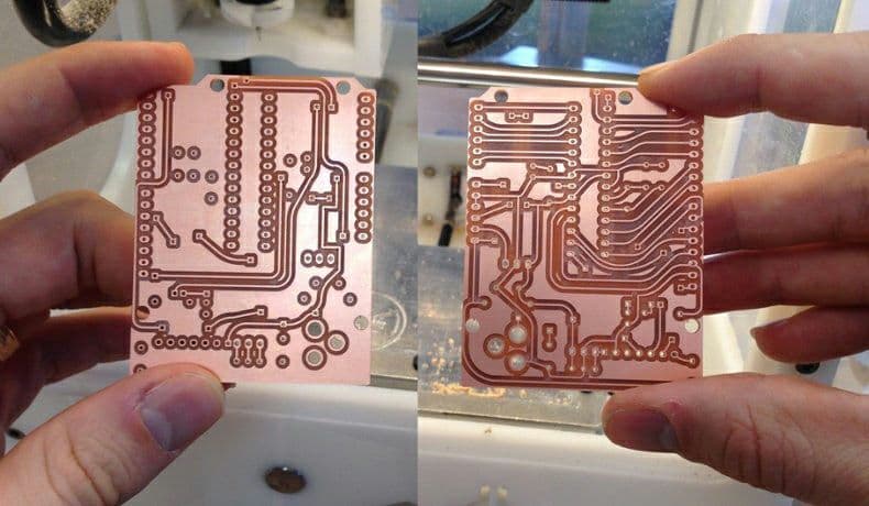
Now, once you're done cutting out the traces for the circuit, re-tool the mill with an End-mill and load in
your outline Gcode. Try to pick one of the End-mill bits that are broken to about half of the original length
as it will ensure that your bit has a lower chance of sheering off midway through the job. Once everything is
done, gently feel the surface, there might be some really sharp burrs, so take the circuit board to some fine
grit sandpaper, gently sand it with light passes, as you might also sand away the very thin copper traces you made.
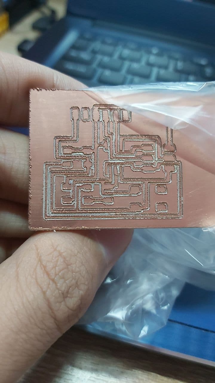
And this is what we have, it is not perfect, but for sticking a small Attiny45 on it, and having it run a
small bit of hello world code, it will do perfectly.
Now comes the hard part, soldering all the components onto the board. Considering this sem focuses on SMD or
Surface Mount type components, majority of the components can as small as a grain of sand, so best not to lose
them. Put them on a brightly coloured mat, and keep it infront of you so you don't knock them onto the floor
with a bunch of other debris or plastic scraps that look just like your SMD components. Here are some of them:
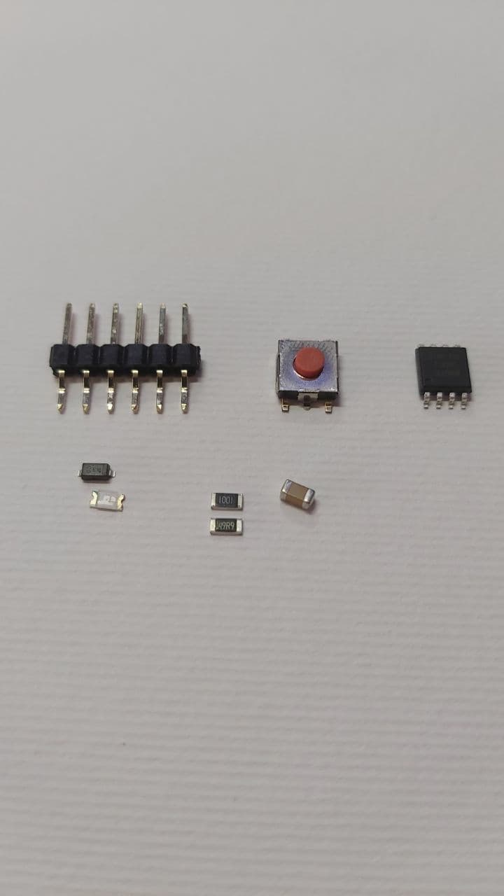
In the top row, we have the Pin headers, a button for reset, and the Attiny 85 IC. In the bottom row we have a Diode
and an LED, two resistors, and a capacitor.
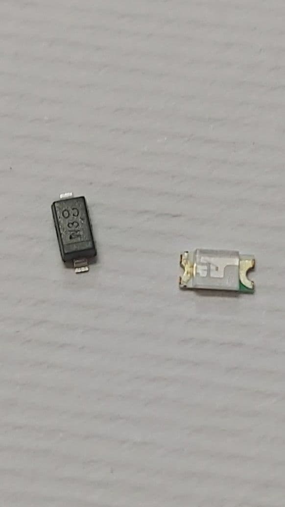
Taking a look at the diode, if you shine a light on it you can see the part number, as well as a thin line across the
bottom. That thin line marks which lead is the cathode, in this case, the one pointing down. As for the LED, there is
a small green mark on the lead, that marks the cathode as well.
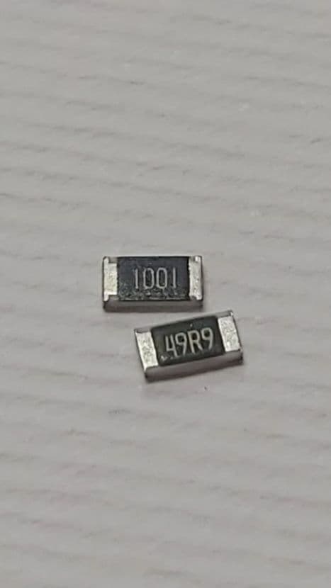
As for the Resistors, the one marked with a 1001 is a 1 KOhm resistor, while the one marked 49R9 is a 49.9 Ohm resistor.
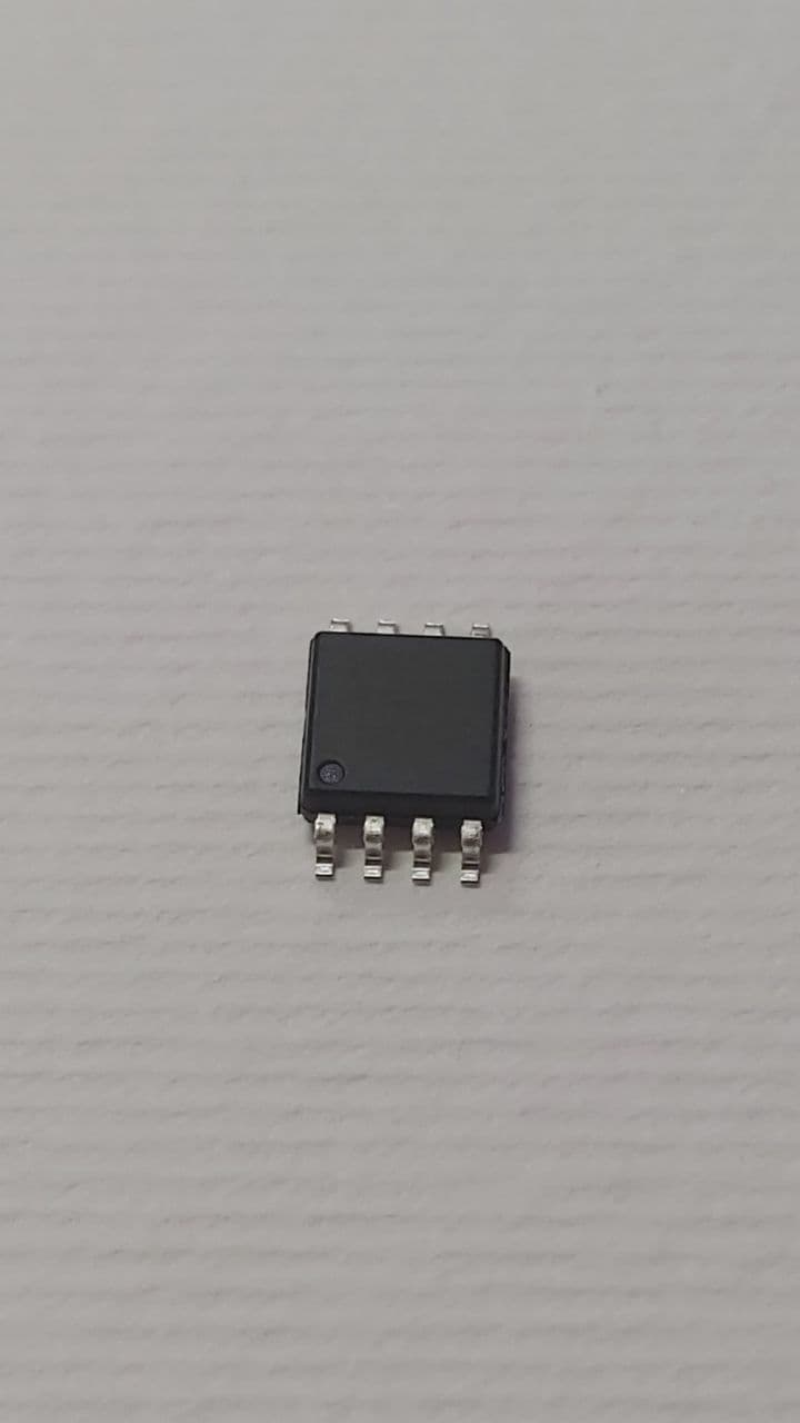
This is the Attiny 85, we will be using this IC in 2 circuits, an ISP unit, and a small microcontroller unit.
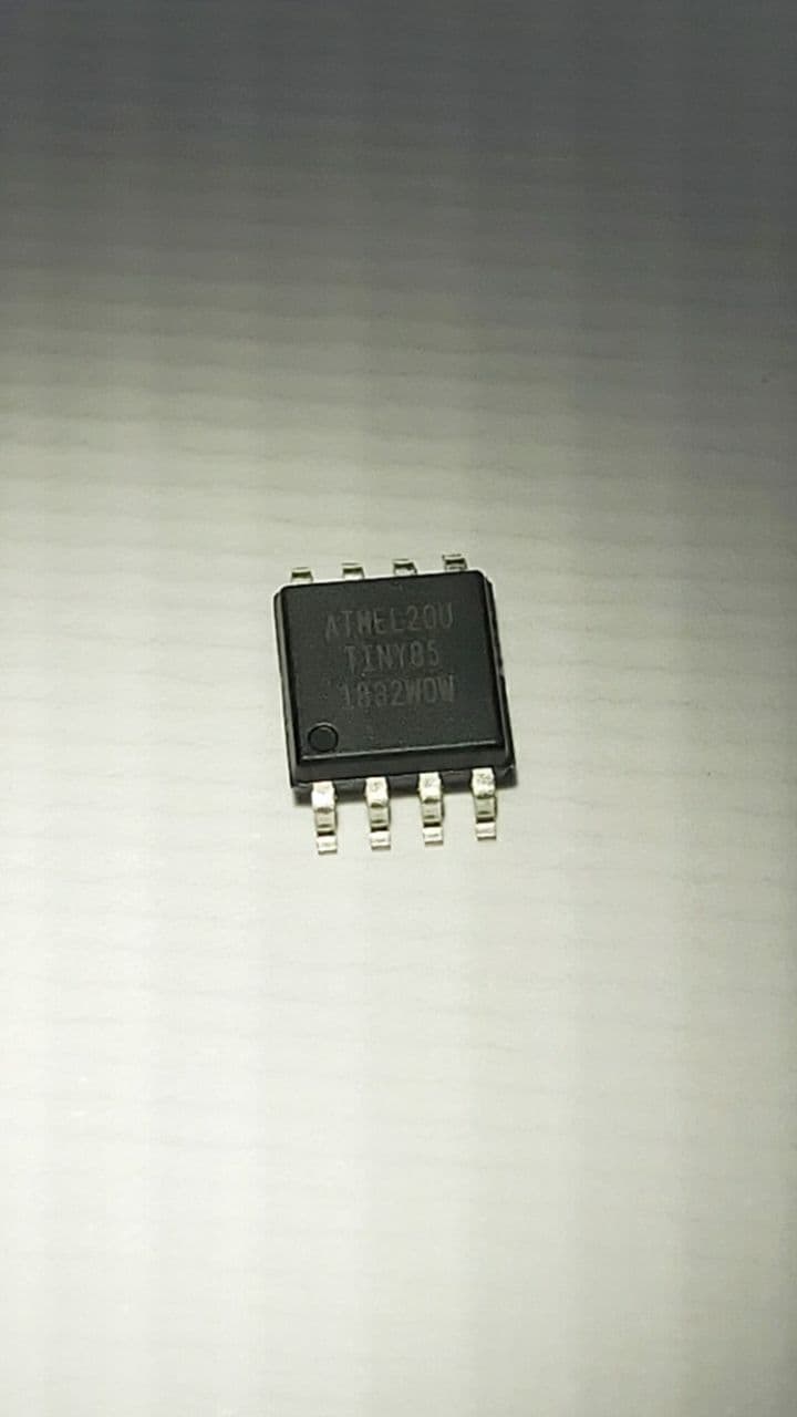
And if we shine a light on it, you can see the part number.
Now soldering them works the same as just about most other circuits, except this time you have to apply some solder
to the board first, get the component in one hand with some tweezers, and the iron in the other hand. The idea is to
anchor the component down on one of its leads first, so you can neatly solder the other lead, and then come back to
the first one. It will take some practice, and a lot of flux. You have to take your time with this as it is very easy
to short out two traces, and near impossible to remove the short without solder wick or a copper brush on hand.
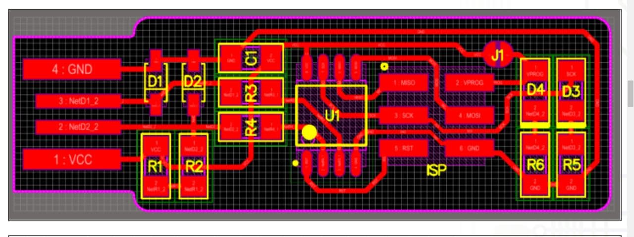
This is the circuit diagram for the ISP unit, take note of the polarity on the diode D1 and D2, and the LEDs D3 and D4
As well as which resistors to use, as well as the orientation of the IC, with the dot marking pin 1.
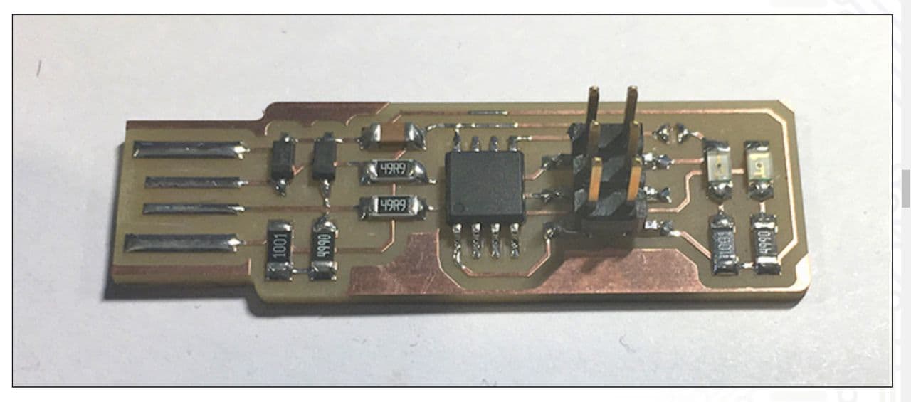
This is the final result, not my best, but not bad for my first attempt at doing any SMD soldering.
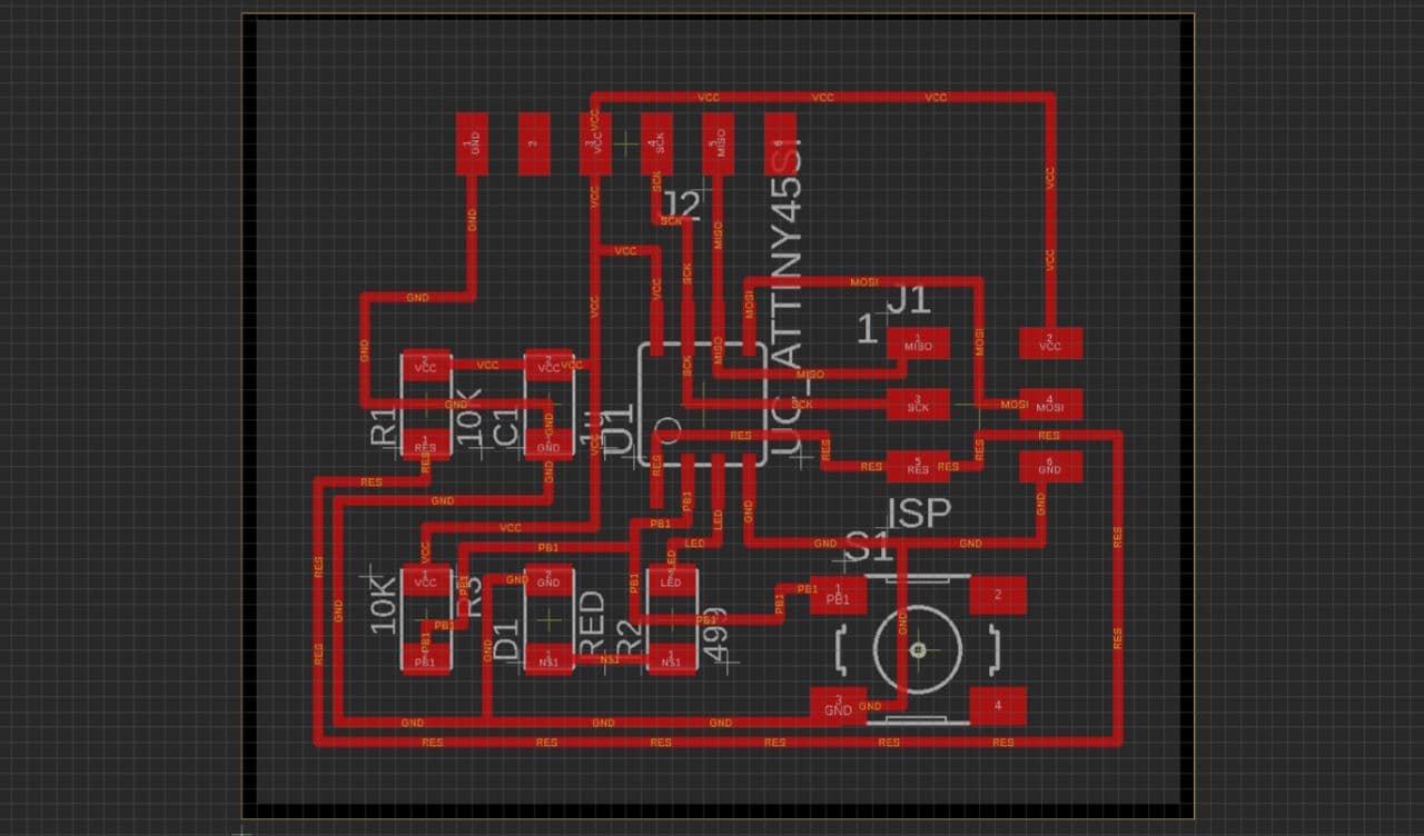
Now for the microcontroller unit. That schematic does not mark the orientation of the LED D1, so you have
to follow the traces. In this case, at D1 the top trace is ground, so naturally that is where the green mark
would be.
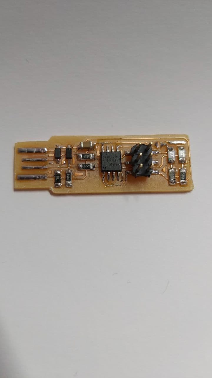
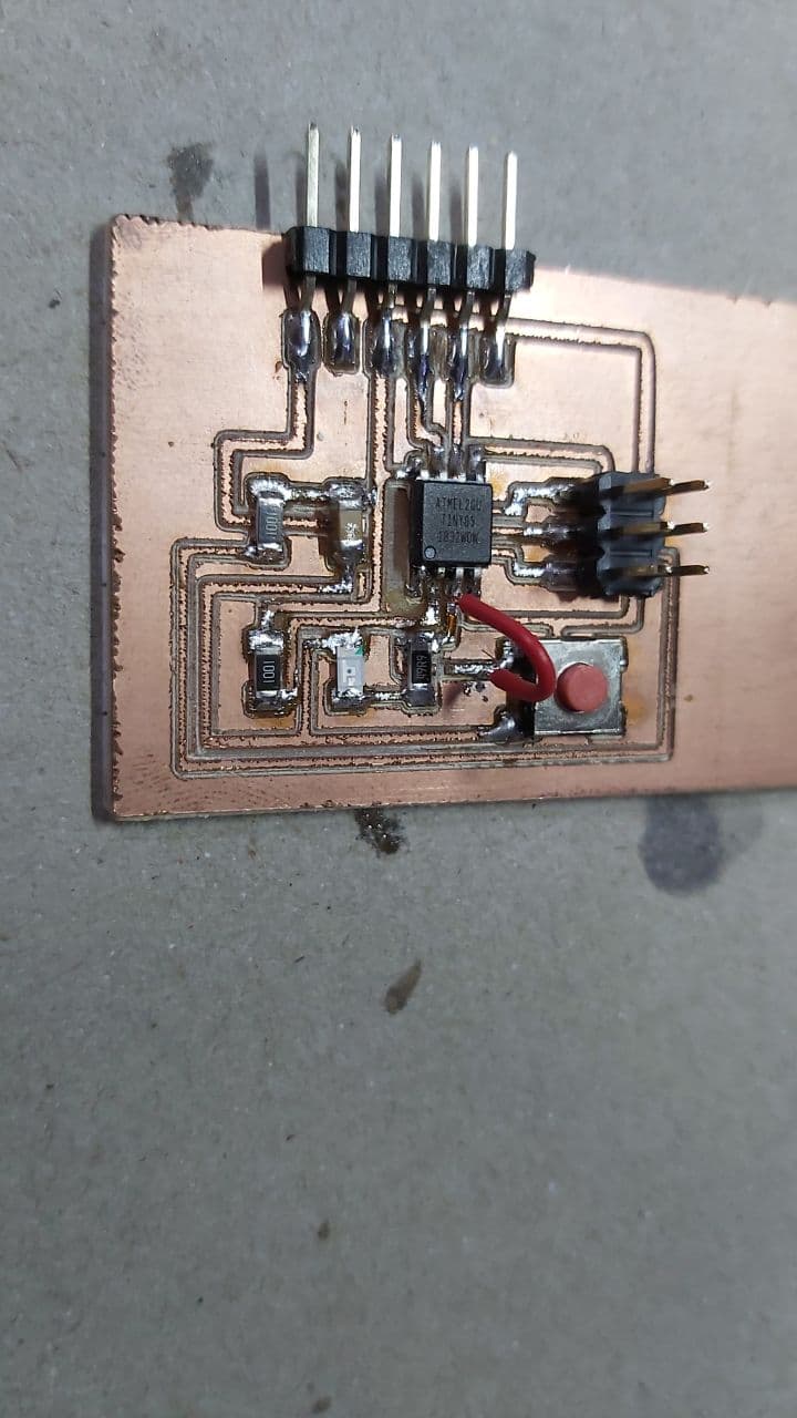
And here is the completed microcontroller board, which soldered surprisingly well given how long I left it out on a shelf
I was very sure it was oxidised beyond the point of no return. If it works well, I might use this for the final project.
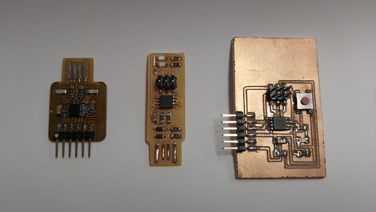
And a final look on all the Circuit boards used in this. When it comes to actually starting the ISP unit, we need a programmer
that already works, which hopefully turns out alright. Also, be sure to scrape off the excess copper around the USB pins on the ISP
unit, leaving it there risks accidentally shorting out the Gnd and 5V pins on your laptop when you plug it in, and maybe cut up an
old credit card and stick it under the USB pins to give the board and your laptop USB port good contact.
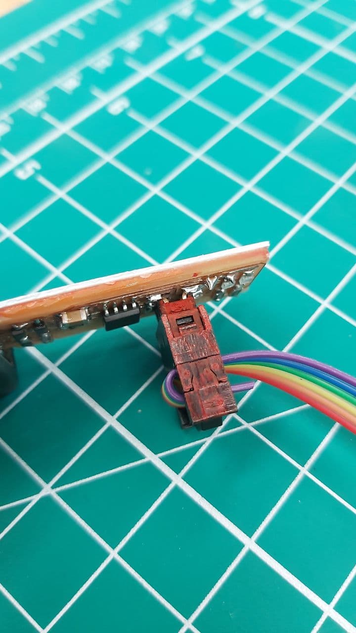
Also, be sure to mark the orientation of your cables with some bright paint,
Edit from about a month after this was written, After about a month of trying to get the toolchain and programmer working, it turns
out there was a Short in that circuit, but thankfully the Attiny85 survived, because if it did not survive, I would have just scrapped
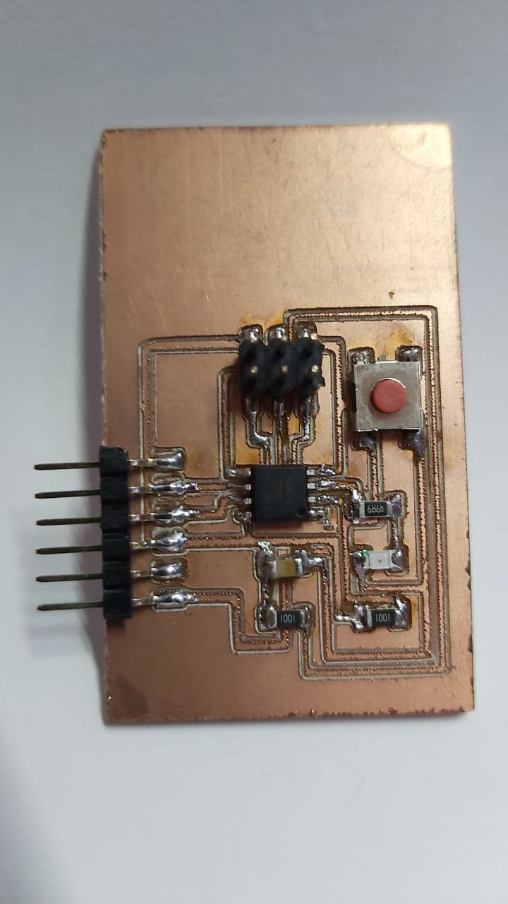
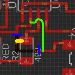
the whole board. What happened in the end was I ran a bypass, in the least organised way.
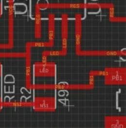
The problem lies here, between that narrow gap between the upper LED pad, and the PB line
The yellow section represents where I shorted it by accident when I soldered it
The blue section represents where I cut the copper traces to isolate the short
And the Green section represents where I ran the Bypass.
As to where this translates to in the actual circuit, this is the affected area.
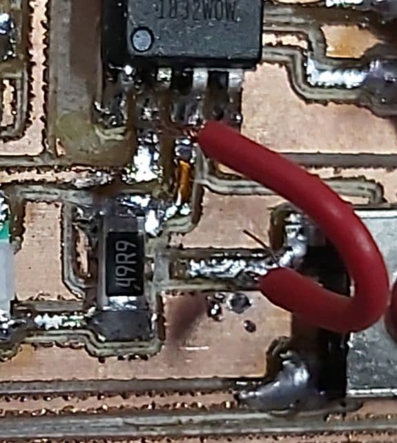
And here is rougly where I made the cut and the bypass.

Interfacing & Applications Programming