Today, we will be designing a small plaque in Fusion 360, and then autoCAD, for reasons
which you will see later on. This is from the video game called "Outer Wilds", this was
an obession of the ancient species, and all over the solar system they draw this symbol.
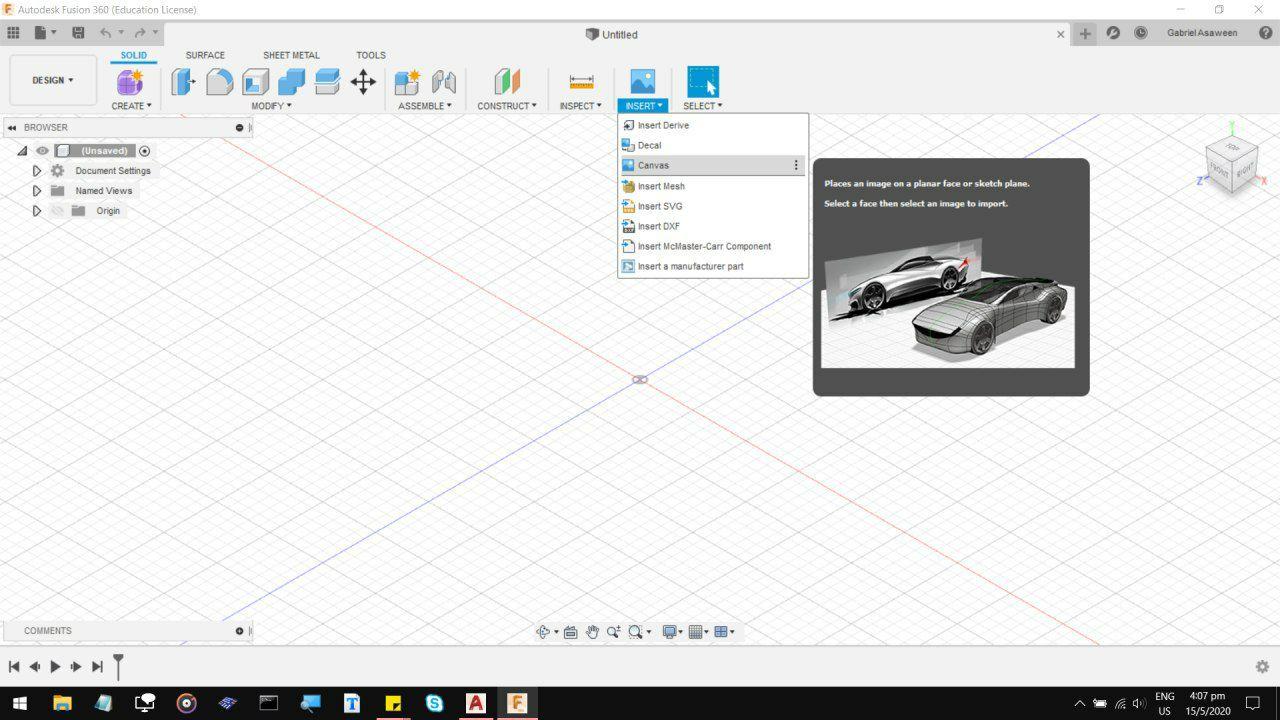
First, we need our reference image. Import one under Insert, Canvas. Browse the file from
somewhere on your computer. I do not think it matters too much if its a Jpg or Png.
Pull the reference image to somewhere generally centered, forget about the scale for now.
Now this is where it gets tedious, I decided to start tracing each barb individually.
There is probably a more efficient way to do this, but this is the way I chose to do
it because the Point Snap setting below allows you to estimate how a 3D printhead might
be restricted when printing the fine details.
After about 40 minutes, I ended up with quite a neat outline of the design.
Originally, I was going to extrude it and print it as a plaque, so I scaled it
up and extruded the piece to about 1cm thickness, and gave it a simple base 1.5cm thick.
It was about that point I started measuring the size of the smallest details,
the smallest triangles are about 0.15mm wide, while the 3D printer extruder
is about 0.4mm wide, which leaves me with 2 options: I can either Scale it up
further, or remove some of the small details.
I decided not to follow through with either of them,
as the Printhead might start melting off the pieces it already laid down, and
the fact that this was already about 15 by 16 cm big, which from past experience
would take about 8 hours or more to print. Additionally, you do lose abit of detail
with 3D printing.
So the next step was to upload the raw sketch in DWG form over into autoCAD.
I think my next plan for this is to cut this out on a clear sheet of acryllic
and then again on a translucent colour like blue or green. I might insert the
coloured pieces into the clear piece. And maybe sandwich that between two blank
clear sheets of acryllic, seal it in with acetone to make it look like a hologram.
Its either that, or just engraving the design in on a light burn setting, and then
cut the perimeter out, so I dont end up wasting too much acryllic. It would look
quite good on a clear sheet, then colour the engraved sections in with a blue/purple
whiteboard marker. But overall, I am fairly satisfied with the base design of it.
Today, we will be designing a simple box for laser cutting. This will be a small
60x60x63mm cuboid shape, 4 walls, ceiling and a floor. I could have just done this
straight in Autocad, but we'll start with fusion 360 just so we can visualise how
the structure looks like in 3D, and then make some edits along the way if needed.
First, start with a base, and 4 cut slots of 3mm thick,
as this will be cut on a 3mm thick material.
Next, draw a sketch over one of the slots and extrude up to create one of the walls.
Now when we extrude a new notch from the wall, for some reason it forms as a separate
body. Make sure to set the extrusion to be a New body and not Join, otherwise hit undo.
To solve this, we will use the combine function. Which is basically a big 'merge' button
that can combine two or more bodies. I used this in another project where I merged 36 cubes,
so it is one of my favourite features.
Now, cut the rest of the slots on the other edges of the wall
After the first wall is finished, use the age old Copy and Paste function, and pull wall copy
over to the opposite side. Its a good idea to build all the sides of the box in pairs, just to
keep things simple for later on.
Now repeat the same process of drawing a sketch, extruding, then pulling the notches out for the 3rd
wall set. Again, the system creates them as 4 separate bodies, so that is where the Combine button comes in
And combine,
And again, copy
And again, paste
Now, select the base body, and copy and pull the base up to be the ceiling.
Now, feel free to sketch and cut a hole out in the top or any of the walls
After checking the box for fits, record down all the measurements, and start redrawing
the plates in Autocad, flatpack style. I have had issues before, so its a good idea to
give each piece a 10mm separation between the edge of the canvas and the other parts.
Here's something important: even though the beam on the laser cutter shoots a hairline thin cut
it still eats away a small amount of material as it cuts. Small enough to miss, big enough to be a problem.
A good idea is to increase the length of Notches by 0.5mm, and to keep the slots around the same length.
That way you can just file or sand off any extras to get a good fit.
After you have all the pieces drawn out, you can edit each piece for any extra designs you need to include.
So naturally, I want to engrave the eye of the universe motif into one of the walls, Just because I can.
Now get the sizes and the scale right,
Save as a DXF file, and we are ready to get it cut.